Facebook
 Google
 GitHub
 Linkedin


I have designed on a breaboard a very simple oscillator: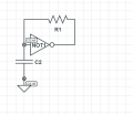
I used a schmitt trigger inverter(not as shown in the diagram,its just that circuit lab doesnt have a schmitt trigger inverter symbol) because with a normal inverter the output is NOT a square wave.I noticed that if the output impedance is low(such as a LED) the circuit doesnt oscillate at all but if the output impedance is high(such as a inpout pin of a arduino nano)circuit does oscillate.
For this particular circuit the duty cycle is exactly 50% with a frequency set by the RC timing constant and the transistion voltage level of the schmitt trigger.How can I make this circuit have a different duty cycle than 50%?Thanks.
I used a schmitt trigger inverter(not as shown in the diagram,its just that circuit lab doesnt have a schmitt trigger inverter symbol) because with a normal inverter the output is NOT a square wave.I noticed that if the output impedance is low(such as a LED) the circuit doesnt oscillate at all but if the output impedance is high(such as a inpout pin of a arduino nano)circuit does oscillate.
For this particular circuit the duty cycle is exactly 50% with a frequency set by the RC timing constant and the transistion voltage level of the schmitt trigger.How can I make this circuit have a different duty cycle than 50%?Thanks.