Schmitt trigger debounce circuit problem(s)

Thread Starter

chaoticbob

Joined Sep 17, 2026
5
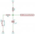
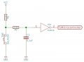
I am trying to build a hardware debounce circuit after Elliot Williams published here. This is his schematic:
proper_debouncing-sch.jpg

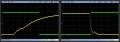
Elliot shows this behaviour:
proper_debouncing_scope.jpg

The right hand trace shows the voltage at the output of the RC stage (yellow) and the trigger (green) when the switch closes, the left hand when it opens again.
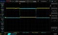
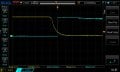
What I get is this
Switch closing:
NewFile2.jpg


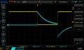
Yellow after RC, blue trigger output. So far so good, but zooming out to see the whole button press:
NewFile1.jpg

Can anyone suggest a reason for this behaviour? I don't understand (a) why the Schmitt trigger doesn't latch to +5V for the duration of the button press and (b) how it swings to -5V (ish) when the button is released.
I'm probably being thick (very new to playing with electronics), any education would be most welcome.
Bob.
 

Attachments

Thread Starter

chaoticbob

Joined Sep 17, 2026
5
Thank you so much MrChips. This was driving me nuts. I suspected it was some stupid newbie thing I was doing wrong. With DC coupling:

NewFile2.jpg

Don't yet understand exactly why AC coupling produced the effect it did, but I expect a bit of research will reveal all.
Thanks again, Bob
 

crutschow

Joined Mar 14, 2008
38,784
Don't yet understand exactly why AC coupling produced the effect it did, but I expect a bit of research will reveal all.
AC coupling places a capacitor in series with the input to block DC.
This means a pulse voltage will decay to zero with a time-constant of that capacitor value (typically in the neighborhood of 100nF) times the scope input resistance (typically 1MΩ).
 

Thread Starter

chaoticbob

Joined Sep 17, 2026
5
AC coupling places a capacitor in series with the input to block DC.
This means a pulse voltage will decay to zero with a time-constant of that capacitor value (typically in the neighborhood of 100nF) times the scope input resistance (typically 1MΩ).
Thanks. That explains the decay after the trigger goes high I guess. Maybe the negative spike I see when the switch opens and the trigger goes low is something to do with the 'scope differentiating the signal. Shall think on it!
Bob.
 

MrChips

Joined Oct 2, 2009
35,157
Here is something that you need to know.
Traditionally, DC and AC meant Direct Current and Alternating Current.

In signal processing, they take on some additional meanings.
DC refers to signals at 0 Hz.
AC refers to signals with frequency greater than 0 Hz.
All signals contain DC and AC components.

With regards to oscilloscope terminology,
DC means all frequencies, 0 Hz and > 0 Hz, DC + AC
AC means that DC is removed, i.e. the signal is filtered using a high-pass filter.

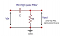
This is the circuit of a simple RC high-pass filter.

1789775877800.png
 

Thread Starter

chaoticbob

Joined Sep 17, 2026
5
Here is something that you need to know.
Traditionally, DC and AC meant Direct Current and Alternating Current.

In signal processing, they take on some additional meanings.
DC refers to signals at 0 Hz.
AC refers to signals with frequency greater than 0 Hz.
All signals contain DC and AC components.

With regards to oscilloscope terminology,
DC means all frequencies, 0 Hz and > 0 Hz, DC + AC
AC means that DC is removed, i.e. the signal is filtered using a high-pass filter.

This is the circuit of a simple RC high-pass filter.

View attachment 371475
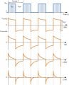
Thanks for your further input MrChips, much appreciated. I still wondered about the differentiation thing though and found an online tutorial which gives an RC differentiator circuit identical to your high pass filter and gives examples of the response of the circuit with various RC values in relation to pulse width:
rc-rc42.jpg

The labelling of these graphs is somewhat confusing - from the context of the article it appears that the label 0.5RC for example refers to a situation when RC = 0.5*(pulse width). The 0.5RC graph closely resembles what I was seeing. Using the numbers suggested by crutschow (C=1e-7F and R=1e6Ω) for the scope's input gives RC = 0.1s, and since the pulse duration (time switch is closed) is ~0.2s this seems to fit.
If I'm completely on the wrong track here please tell me, but if not it may be an alternative way of looking at the scope's response.
Bob
 

MrChips

Joined Oct 2, 2009
35,157
You are on the wrong track.

The pulse duration and RC values are independent. They have nothing to do with each other.
You can stretch out the period T as long as you wish. Pay attention to only one transition, for example, one rising edge.

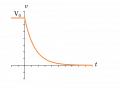
The shape of the decay curve is always the same, a decaying exponential function.
1789865755430.png

What changes is the the length of time it takes to decay, and it depends entirely on the value R x C.
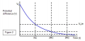
At 1RC, the voltage has fallen to 37% of the starting voltage.

1789865987550.png

The graph you have shown in post #8 is misleading.

If the ON time were 10 x RC time, the curve would look like the 0.1RC curve.
In other words, if we change the RC values to 1/10 the initial RC values, the curve would look like the 0.1RC curve.

What you see on the oscilloscope depends on perspective, i.e. the time scale on the oscilloscope. By changing the oscilloscope's time scale, you are zooming in and out of the waveform. RC value stays the same.
 

AnalogKid

Joined Aug 1, 2013
12,266
Thanks for your further input MrChips, much appreciated. I still wondered about the differentiation thing though and found an online tutorial which gives an RC differentiator circuit identical to your high pass filter and gives examples of the response of the circuit with various RC values in relation to pulse width:
Nice find, and excellent graphic. It shows clearly that differentiation as a distortion of the original waveform, and how the amount of distortion is related to both the pulse width and the R-C time constant. Intentional and useful, but still a distortion. Same for integration.

Also, " The pulse duration and RC values " are not independent, because the trailing edge of the pulse train cuts off the exponential decay from the leading edge. The pulse width has nothing to do with the shape of the decay waveform, but it does determine how long the decay is allowed to go on before being truncated.

ak
 
Last edited:

MrChips

Joined Oct 2, 2009
35,157
@AnalogKid has a better way of explaining it. The shape of the discharge curve is always the same, based only on the R x C values. The discharge sequence is truncated by the negative transition, i.e. it is cut short by the end of the high pulse. You don't get to see the capacitor being completely discharged. The negative going signal (start of the low pulse) switches the voltage to a negative and hence starts a new discharge cycle with negative voltages.

Note that the high pass filter performs the same mathematical function as differentiation.
Differentiation looks at the current and voltage in time space.
Filter functions look at the AC behaviour in frequency space.
 

Thread Starter

chaoticbob

Joined Sep 17, 2026
5
Thanks for further comments @MrChips and @AnalogKid.
I wasn't actually conflating pulse duration and response to the initial 'impulse' (in my own mind at least), it was just a dim recollection of RC circuits as analogue differentiators/integrators that led me to the article I cited, and the similarity of the '0.5RC' graph to my observations that made me think there must be something in it.
Munching on my marmalade and toast at breakfast today (I'm British) it occurred to me that @MrChips was thinking in the frequency domain whereas the differential view is couched in the time domain. I think that's why I said the differential approach might be an alternative way of looking at the same thing. Reading responses tonight it seems I wasn't entirely on the wrong track.
Anyhow, my practical question was answered in the very first reply for which I'm most grateful. I can now get on with my project without worrying about the button debouncing circuits.
 
Top