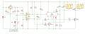
My version with a CD4017 counter.
When first powered ON pin3 of IC2 is High (indicated by the red LED), circuit is in the reset mode, both relays OFF.
When the switch is pressed both outputs of IC1 go High. IC1B activates relay K1.
IC1A sends a pulse to IC2 and pin2 goes High which activates relay K2.
Relay K1 stays activated as long as the switch is pressed. When released K1 drops out but K2 stays activated.
The next press of the switch sends a second pulse to IC2, pin2 goes Low causing relay K2 to drop out.
When pin2 is Low diode D1 prevents Q1 from conducting inhibiting relay K1 from activating a second time.
At this same time pin4 goes High sending a pulse through diode D3 to reset pin15 returning the circuit as when first powered ON.
Operation verified on the breadboard.
Sw1 is the Ignition switch.
Only need this one control board connected to the switch, the relays can be remote located if need be.
Speaking of relays, need to know how much current the coils draw. Any part number or link?
Before you start a complete rebuild why not try and troubleshoot the existing circuit since you have a meter.
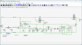
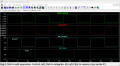
Below is the original circuit, the Black numbers represent the voltage at those locations when the switch is not pressed.
The Red numbers when the switch is pressed and held.
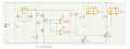
I wasn't sure if you wanted two circuits or one. Anyway...
This circuit operate a little differently in that it uses a long and short press of PB:
A short press of PB does nothing but energize/deenergize K1 (Start).
A long press of PB energizes K1 and causes K2 to latch (Start->Run).
If K2 is latched, a second press of PB resets K2 (Run->stop).
Cycle then repeats if PB is pressed again.
The long press is set for 3 sec but can be easily adjusted shorter or longer time.
It uses three chips: 1-LM358, 1-CD4013B, 1-CD40106B
Sw1 is the Ignition switch.
Only need this one control board connected to the switch, the relays can be remote located if need be.
Speaking of relays, need to know how much current the coils draw. Any part number or link?
Before you start a complete rebuild why not try and troubleshoot the existing circuit since you have a meter.
Below is the original circuit, the Black numbers represent the voltage at those locations when the switch is not pressed.
The Red numbers when the switch is pressed and held. View attachment 362743
Sw1 is the Ignition switch.
Only need this one control board connected to the switch, the relays can be remote located if need be.
Speaking of relays, need to know how much current the coils draw. Any part number or link?
Before you start a complete rebuild why not try and troubleshoot the existing circuit since you have a meter.
Below is the original circuit, the Black numbers represent the voltage at those locations when the switch is not pressed.
The Red numbers when the switch is pressed and held. View attachment 362743
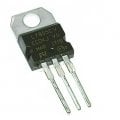
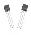
OK a quick update - first L78L05 read 4 v, second 13v, right out of the amzn package, 4th one with 5 v.
At the Trigger connection I am measuring 1.74v open and 1.2v pushed...but...
stuck at the 12k ohm resistor, it measures 12 ohm, but no voltage on the other side of it indicating an open circuit somewhere
I did that 5v then zero, after the board sat a coule hours un touched, now the L78L05 has 13v in and zero out, it workes all afternoon, as I kept checking it...
Would appear the 78L05 regulators are probably fakes, unless there's an intermittent short somewhere on the output of the chip.
To be clear you hooked up the circuit in post #44, correct?
Is this circuit on a breadboard?
If it was hot that would normally indicate a short on the output some where.
The regulators might be OK as they have short circuit protection.
Are you sure the regulator is installed correctly?
What are the HC versions?

 Facebook
 Google
 GitHub
 Linkedin