How to make a 20 LED chaser with 4017 ?

dl324

Joined Mar 30, 2015
18,404
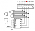
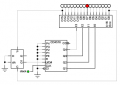
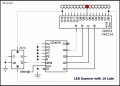
Here's a 16 LED circuit using a binary counter and a 4to16 encoder:
1716525768948.png
You can make it more interesting by using a binary rate multiplier (CD4089) to change the frequency so the dot moves faster for the center counts. The encoder can be CD4514 (or CD4515 for the opposite polarity).

I breadboarded this in the 70's, but I don't have a schematic or the breadboard available at the moment.

I envisioned using it as a pendulum for a grandfather-type clock that I never got around to building.

EDIT:
Circuit simplification based on learnings from the 32 LED version:
1716820942354.png
 
Last edited:

dl324

Joined Mar 30, 2015
18,404
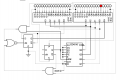
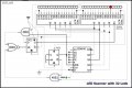
Here's a 32 LED version:
1716780161489.png
I don't know of a commercial 4:16 encoder with enable.
EDIT:
CD4514/5 do have an enable/inhibit.
Note that the D and clk inputs of the direction flip flop aren't connected. The Digital Works simulator connects unconnected inputs to ground.
 
Last edited:

Thread Starter

q12x

Joined Sep 25, 2015
2,227
Sorry for the delay in my response.
Here's a 16 LED circuit using a binary counter and a 4to16 encoder:
+
I don't know of a commercial 4:16 encoder with enable.
I believe there is the problem. It is a DE-coder, is decoding the input binary into Decimal.
The ENcoder is your 4516 which I never worked with, which is creating a binary output per each clock pulse.
then +
I breadboarded this in the 70's, but I don't have a schematic or the breadboard available at the moment.
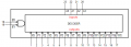
I looked into my ICs and I only have 1 model this CD4514 = 4 to16 line decoder/demultiplexer
It also has 1 input Enable and 1 input LE (Latch Enable)

I also find another one 74154 (which I dont have)
It also has two input enable (E0 and E1)
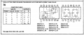
1716845443119.png

i believe you also mentioned this CD4515
The encoder can be CD4514 (or CD4515 for the opposite polarity).
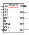
1716846132162.pngCD4516 is a binary counter and is a correct encoder for the cct.
But your CD4514 or CD4515 are not encoders. They are decoders.

You can make it more interesting by using a binary rate multiplier (CD4089) to change the frequency so the dot moves faster for the center counts.
Interesting! I never seen one. I will give it a try in my sim someday.

I made a Better Rez img of your cct and with --Proper Notations--.
Always put the BEST rezolution image of your cct ! And always put all IC names in your ccts. As a general rule for yourself later and for others. It is my gen rule so Im teaching my experience to you.
I also put MY FF 7473 + its correct notations S=Set and R=Reset. It must
But I never test this cct, I only modified the picture.
So....Im not sure of the wire connections if they are good, because I specified new ICs in cct.
dl324-LED Scanner with 16 LEDs and 4514 BCD.jpg
Very interesting how you linked [FF] Data and CLK pins to GND !!!!!!!
Very interesting use of the [FF] too, so it will switch not from the clock pin (because is grounded) but only from its Set and Reset pins ! WOW! That is very clever!
--------------
But I get your idea. If I want "MORE" Leds for a LED_Scanner_cct, I can use these decoders.
The original idea was to play with the 4017 (which I like it very much for its simplicity) and squeeze all it can got.
Your idea is not bad for a Scanner LED cct !!! I like it. Again, I will have to test it in my Proteus simulator.
If any ideas pop out, do share.
Thanks. Very good !
--------------
Addendum
I definetly not sure of the wiring for your second version, the cascaded LED_Scanner_cct with 32 Leds.
Again Im reposting the HiDef Version of your images. Please make sure to do it yourself from now on. If you dont know how, just ask me and I will help you.
Also I changed the IC models, to fit what I have. (except 4001-I dont have any NOR gates). The first FF 7473 wiring..... Im not convinced is correct.
So please look into the cct correctness and tell me what to change.
I WILL put these ccts in my sim in the end, and I will obtain the correct wiring then. Right now I made a pretty picture only. Hehe.
I notice your 2nd FF D and CLK pins were floating.... they are inputs, and they should definetly be linked to GND (like in your 16_Leds version)
Specifically for my FF 7473 that I have, I must tie to + rail its S and R pins, so I modified your cct from this pov. (We will know better after simulation)
dl324-LED Scanner with 32 LEDs and 4514 BCD.jpg
 
Last edited:

dl324

Joined Mar 30, 2015
18,404
But your CD4514 or CD4515 are not encoders. They are decoders.
The definition of encoder and decoder never made sense to me and I use them pretty much interchangeably.
I made a Better Rez img of your cct and with --Proper Notations--.
What isn't readable in the images that I posted? That's what I get when I use the snap shot tool and paste the image into the browser. I'll see if saving as an image file first makes a difference. (EDIT: makes no difference.)
And always put all IC names in your ccts. As a general rule for yourself later and for others. It is my gen rule so Im teaching my experience to you.
The decoder/encoder I used was a component I made and it doesn't have any commercial equivalent. I don't add component designators because I'd have to do that manually. I started adding pin numbers to new components, but don't have much interest in modifying components I've already created.

You labeled the AND and NOR as their CD4xxx equivalents, but the gates I'm using are built-ins and I'm not inclined to label as CMOS or TTL equivalents. That's too much work. The simulator I use doesn't differentiate between logic families (or fan-out).
I also put MY FF 7473 + its correct notations S=Set and R=Reset. It must
Set/preset and reset/clear are synonyms. I use them interchangeably.
I definetly not sure of the wiring for your second version, the cascaded LED_Scanner_cct with 32 Leds.
What isn't clear?
I notice your 2nd FF D and CLK pins were floating.... they are inputs, and they should definetly be linked to GND (like in your 16_Leds version)
The simulator I use connects any unconnected inputs to ground. I should have mentioned that or connected them explicitly for those who don't know that inputs shouldn't be left unconnected.
The original idea was to play with the 4017 (which I like it very much for its simplicity) and squeeze all it can got.
Your idea is not bad for a Scanner LED cct !!! I like it.
I understand that you wanted to use CD4017, but an up/down counter is more appropriate. once you got past 5 LEDs.
 
Last edited:

dl324

Joined Mar 30, 2015
18,404
Specifically for my FF 7473 that I have, I must tie to + rail its S and R pins, so I modified your cct from this pov. (We will know better after simulation)
I assume you meant 7474. Preset and clear are high active on my symbols so you need inverters on the flip flop that changes count direction.

TI uses preset and clear and the bubbles on those inputs indicate LOW active.
1716916569714.png
 

Thread Starter

q12x

Joined Sep 25, 2015
2,227
I assume you meant 7474.
You assume wrong. I have both of them and I specifically choose 7473 because is a J-K FF and is in acordance to your cct, while 7474 is a DTFF and is not in accordance to what you have used there. Thats my reasoning. I was folowing your cct but with the ICs I have.
What isn't clear?
I misspell, I meant "your" cct that I rebuild it with my components and the wiring in what I made. Hope is right.
The definition of encoder and decoder never made sense to me and I use them pretty much interchangeably.
explain in more detail, I want to see what you see. For me they are VERY distinctive but maybe Im a noob at them compared to you.
I'll see if saving as an image file first makes a difference. (EDIT: makes no difference.)
Find a way to make it bigger size as a file alone and then post it in the forum thread. Trust me, its better at bigger rez and you will get used to it in time. You should trust my word; im a profesional artist afterall, with absolutly no money for 11years.
I should have mentioned that or connected them explicitly for those who don't know
always connected them explicitly !
TI uses preset and clear
Hmmm, its not new to me and I have seen these (and others) notations but I stopped at Set and Reset. For me it has more sense and more easy to remember and to visualize in my mind. I suppose its a matter of "getting used" to a certain mentality in the end. For me preset and clear does not click - at all ! Haha.
 

ElectricSpidey

Joined Dec 2, 2017
3,342
To make a 20 LED chaser using a 4017 decade counter, connect the clock input of the 4017 to a 555 timer configured as an astable oscillator to provide a continuous pulse signal. The 4017 has 10 outputs, so to control 20 LEDs, you'll need two 4017 ICs. Connect the carry-out pin (pin 12) of the first 4017 to the clock input (pin 14) of the second 4017. Connect the LEDs to the output pins of both 4017 ICs, with the cathodes to ground through current-limiting resistors. Ensure to reset the second 4017 at count 10. This way, as the clock pulses, the LEDs will light up one by one in sequence from 0 to 19, with only one LED on at a time.
Sorry, but that won't work.
 

dl324

Joined Mar 30, 2015
18,404
You assume wrong. I have both of them and I specifically choose 7473 because is a J-K FF and is in acordance to your cct, while 7474 is a DTFF and is not in accordance to what you have used there. Thats my reasoning. I was folowing your cct but with the ICs I have.
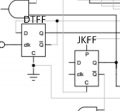
I used a D flip flop.
For me preset and clear does not click - at all ! Haha.
Manufacturers are going to label pin functions the way they want to, and you need to be able to adapt.
 

Thread Starter

q12x

Joined Sep 25, 2015
2,227
I used a D flip flop.
This is how I interpret it originally, when I first see it.
1717012432106.png
I might had interpret those P and C notations that im not so used to, as J and K.
But now when you mentioning is only DTFF, I stop and think and I realized you are right, because there is DTFF with S and R.
I definitely didnt see it. Totally my mistake. Well, another undesired lesson. With this mistake now, I will be more careful in the future.
Interesting.
1717012796235.png
 
I agree they are plenty... but not what I want.
If you mean this cct version:
View attachment 321000View attachment 321003
This type of cct is good as a clock.
Well, When A is clocking B is not doing it sequentially, meaning 1 after 1 (or one after another), but binary, meaning when A is finishing a pass, it will increment B with 1 and then A will start another round.
It is counting 0123456789 in A then 11 in B. (since 10 was lit up until this time) then again 0123456789 in A then 12 in B (since 11 was lit up until this time) and so on.
All I want is an incremental and cursive 0 1 2 3 4 5 6 7 8 9 10 11 12 13 14 15 16 17 18 19 20
what is the name of the simulation bro ? I want to try some circuit online so i can wired it in a breadboard or PCB
 
I agree they are plenty... but not what I want.
If you mean this cct version:
View attachment 321000View attachment 321003
This type of cct is good as a clock.
Well, When A is clocking B is not doing it sequentially, meaning 1 after 1 (or one after another), but binary, meaning when A is finishing a pass, it will increment B with 1 and then A will start another round.
It is counting 0123456789 in A then 11 in B. (since 10 was lit up until this time) then again 0123456789 in A then 12 in B (since 11 was lit up until this time) and so on.
All I want is an incremental and cursive 0 1 2 3 4 5 6 7 8 9 10 11 12 13 14 15 16 17 18 19 20
While using it, we still attached the 16th and 8th Pin into the VCC and GND for the two ICs to work, right?
 

dl324

Joined Mar 30, 2015
18,404
Welcome to AAC!

Did you notice the warning that this was an old thread?
what is the name of the simulation bro ? I want to try some circuit online so i can wired it in a breadboard or PCB
He's using Proteus. It isn't a free simulator. I'm using DigitalWorks which is, but it doesn't have any useful commercial parts. You have to make your own.
While using it, we still attached the 16th and 8th Pin into the VCC and GND for the two ICs to work, right?
Not all logic simulators and schematic editors show explicit power and ground connections.
 

MisterBill2

Joined Jan 23, 2018
27,741
Certainly there are ways to deliver a "chase" effect, one was discussed here a few weeks back.But ganging two 4017s will produce a two decade counter rather than a 20 unit chaser.
The scheme was clearly shown quite a few months back in the circuit of a NO HANDS LED CLOCK. There is more logic required as well as driver transistors, so it is not trivial. The scheme IS both obvious and logical, however.
 

panic mode

Joined Oct 10, 2011
5,087
the second 4017 is used to multiplex groups of 10 LEDs. it could be just a FF. and i would not use LEDs like that, current limiting resistor can be added in collector circuit.

another possibility is to just use single 555 and single 4017 and transistor(s) from 555 output.
though this would change counting order (1,11,2,12,3,13,4,14,5,15...)

1768311157666.png
 
Top