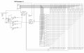
How to make a 20 LED chaser with 4017 ?

Thread Starter

q12x

Joined Sep 25, 2015
2,227
I fly over the page and is a lot to read. Ill have to make some time for it to read it.
-
Something I came up with a long time ago:
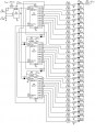
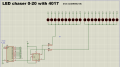
- I duplicate your cct in my Proteus sim, the cct didnt work for awhile with some strange errors, until I put that 1k res for all LEDs. I overlook it. Then, IT WORKED. The error was that first and last IC were running in the same time while the middle was completely off. The issue was that too much current was surging through the LED (that was ON) and the IC was starved of current and got nuts and misbehaved. We learn from errors! But realistically, all those LEDs were burned one by one (hahaha) if it was in reality, so they have worked for one time only. Its good we have simulators !
- I also simplified your cct from those extra tr for the LEDs. This IC should drive those LEDs by itself. You made some NOT gates using those tr, but is an over complication in my opinion. Im not sure what kind of leds or consumers you had in your older project (I still have to read it) but if the LOAD was other than LEDs, then yes, adding those tr will have helped to properly drive a higher LOAD.
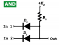
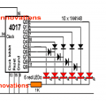
- I was very skeptic about those diodes, but after I managed to make the cct work correctly, I realized those are actually AND gates made from diodes, 1714547977335.pnglike someone else here suggested a few posts back. Your cct stands as an alternative, but is the same in mechanics as the TexasInstruments one. Still 8 leds per chip !
What matters, is that is functional. And I like functional, hehe.
Yes, good job and thanks for the contribution. Cool challenge.
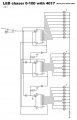
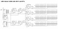
LED chaser v4 0-100 with 4017+ discrete diode AND gate.jpg
 
Last edited:

Thread Starter

q12x

Joined Sep 25, 2015
2,227
..my LED's are extremely bright, so I don't need any extra transistors to supply current ...
For super bright LEDs you dont need a resistor per each LED either. Is enough a single one like I correct it in my previous sketch. These are new generation (well, from 2010 or so up) and they can work with 100uA (u=micro) ! And you will lit only 1 at a time so your cct will consume about 20mA , 10 for the chips and 10 for 1 led thats is switching. You can check the corrected cct in #23. Oh, I believe you are surging the current through the FF so 2 resistors, 1 per each negative branch then. Interesting approach with surging through the FF directly ! Good idea. It's 1 led at a time after all. And you are driving 20 LEDs in the same time.
I just test your cct and is working splendidly ! -Thank you ! Very nice!
1714588501416.png
Can we expand it for more # of LEDs? I did it myself with another 4017... but I was thinking to throw another FF so we will expand to 40.
I believe we can use the Set and Reset of the FF.... but I didnt worked very much with these pins, besides linking them to power rail. Hmmm...
My imediate thought is to put 3 FF's 1 that is commanding the other 2. Hmmm...
Aaaaaaaaaaaaaaaaaaaaaaaaaand Solved ! It turns out it needs 4 FFs + the Set and Reset use for this specific functionality. Not bad. Hihihhi and I did it alone !
Check this out:
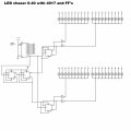
LED chaser v1  0-40 with 4017 and FF.jpg
So the logic is like this: If the Set and Reset are Hi(5V), the FF is Activated; if Set and Reset are Lo (0v) the FF is Off.
 
Last edited:

sarahMCML

Joined May 11, 2019
699
For super bright LEDs you dont need a resistor per each LED either. Is enough a single one like I correct it in my previous sketch. These are new generation (well, from 2010 or so up) and they can work with 100uA (u=micro) ! And you will lit only 1 at a time so your cct will consume about 20mA , 10 for the chips and 10 for 1 led thats is switching. You can check the corrected cct in #23. Oh, I believe you are surging the current through the FF so 2 resistors, 1 per each negative branch then. Interesting approach with surging through the FF directly ! Good idea. It's 1 led at a time after all. And you are driving 20 LEDs in the same time.
I just test your cct and is working splendidly ! -Thank you ! Very nice!
View attachment 321385
Can we expand it for more # of LEDs? I did it myself with another 4017... but I was thinking to throw another FF so we will expand to 40.
I believe we can use the Set and Reset of the FF.... but I didnt worked very much with these pins, besides linking them to power rail. Hmmm...
My imediate thought is to put 3 FF's 1 that is commanding the other 2. Hmmm...
Aaaaaaaaaaaaaaaaaaaaaaaaaand Solved ! It turns out it needs 4 FFs + the Set and Reset use for this specific functionality. Not bad. Hihihhi and I did it alone !
Check this out:
View attachment 321391
So the logic is like this: If the Set and Reset are Hi(5V), the gate is Activated; if Set and Reset are Lo (0v) the gate is Off.
Very nice extention! I had all the separate resistors on my LED's because they were already soldered on from previous use, otherwise I'd have used just one for each as well!
 

MisterBill2

Joined Jan 23, 2018
27,717
OK, and I am very much pleased that others have created different versions of my concept. I was toggling the FF with every clock pulse to the counter, which keeps the flashing more in sequence. The other scheme using the carry out produces a different sequence of lights.
My target was to do it with a minimum parts count.
I am impressed!! Good Job, folks!!
I really am going to need to get that lightning damaged cad box running again. But at least a few folks can visualize a circuit from a "words" description.
 
Last edited:

Thread Starter

q12x

Joined Sep 25, 2015
2,227
2 4017s can handle 100 LEDs using the same principle.
I made already a version with 100 LEDs and 2x2017 but with transistors.
- Im curious how you will do it with FF's ? I am trying right now and it gets complicated very quickly.
- Can you make a cct ?
While waiting for you, I made one but it is quite complicated. It turned out as 0-200.
I'll wait for your cct then I will post mine. Yah...very nice playground and I learned some good stuff with this occasion.
 
Last edited:

Thread Starter

q12x

Joined Sep 25, 2015
2,227
Next question !
- How to make it reversible?
Im imagining a FF with 2 tr on it's outputs for both directions. The wiring will be completely inversed, but the functionality will be from these 2 tr's. This is the basic idea. But I dont know how to implement it ... yet. I will try my best, but Im asking you to come with other ideas as well, with stuff that you experienced, consecrated and classic cct's that you may know, but are completely alien to me. Thanks.
Like Knight Rider 1714721374214.png
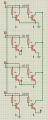
After a little bit of researching, I find this very cheap and easy to make solution. The only downside is that, it is halving the output pins used. Lucky me, I have plenty of outputs I can use already. Its an interesting trick and concept. If you follow each output through each diode, you will understand the functionality. Ok, so this is doable.
1714721084898.pngNow, Im thinking - How to cascade this and make it for more than 6LEDs ? Hmmmmm....
Yes! I made it but is not as simple as the Diode one ! But is doing the thing and is scalable.
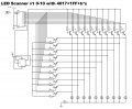
I couldn't put only 1 res for all 10 tr bases, it didnt want to work like that, so 1 res per each tr let it worked.
LED Scanner v1 0-10 with 4017+1FF+tr's.jpg
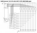
And v2. Those diodes are necessary because the Output is Sourcing but also is Sinking. So I made them "Sourcing Only" this way.
LED Scanner v2 0-10 with 4017+1FF+4081AND gate.jpg
You wouldn't believe how complicated it gets for a 0-20 ! Ohohhoa... I have no idea how to make it, but im sure it can be made.
 
Last edited:

Thread Starter

q12x

Joined Sep 25, 2015
2,227
New challenge !
Think for a LED Scanner containing 20 LEDs driving it using logic gates and FF's.
Im already on it for probably 5h and I still didnt figure it out. Its very hard.
See if you can find a solution.
 

Thread Starter

q12x

Joined Sep 25, 2015
2,227
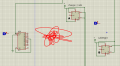
When 4017 is activating Q0-Q4 pins, I need a -SINGLE- Clock pulse to be generated by something (the red squiggle) that will clock those A&B FF's.
The sequence I need is like this:
Q0 = A0 B0
Q1 = A1 B0
Q2 = A1 B1
Q3 = A0 B1
(where 0 = no clock pulse or no change, and 1=one pulse clock, as 0-1-0, starting and ending at 0 and only once)
1714751953621.png
My first thought is AT28C64 ! hahaha- but is overkill - I want something a bit more cheap.
--
Before I tried it like this ...and I realized I need that 1 pulse.
1714753260371.png 1714754369455.png
 
Last edited:

MisterBill2

Joined Jan 23, 2018
27,717
A different approach would be to use a binary UP/DOWN counter with a separate decoder . That could be a CD4516 (binary) or CD4510 (BCD) IC, which may no longer be available. or even a CD4029up/down counter. The binary counters, plus a decoder, can be used to count zero to15.
 

Thread Starter

q12x

Joined Sep 25, 2015
2,227
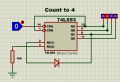
so....I used these pos/neg edge triggers that creates a single very short pulse
but some worked some not. First on the top didnt clocked the A_FF but the second did clock it.
While the 3rd clocked B_FF and the 4th didnt.
I believe this is a simulator problem or bug possibly.
I need a more decisive pulse than this, is my conclusion.
So to be clear, when 4017 switches one of its Q0-Q4, that signal will create a pulse to one of the FF Clock. So it will not remain as 1 but a sequence of 010 quick enough and high enough to 5V as possible. I believe my edge triggers here are not doing it to 5V. Or I might be wrong, but they dont work like they suppose to.
Screenshot_1.jpg
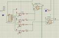
And this is how it looks, this entire 20 LED Scanner cct:
I simplify it as much as I could. See if you can come with a better design/solution. -Very hard !
LED Scanner v3 0-10 with 4017+1FF+4081AND gate - Copy.jpg
 
Last edited:

sarahMCML

Joined May 11, 2019
699
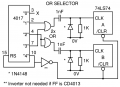
This is the pulse output version of the circuit I suggested earlier this morning!

OR_Selector.png

If you don't have any OR gates, just use NOR's and put the 2 unused gates on the outputs as inverters!

EDIT: Finally, THE correct version!!!!
 
Last edited:
Top