 Facebook
 Google
 GitHub
 Linkedin
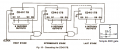
How to make a 20 LED chaser with 4017 ?
- Thread starter q12x
- Start date


| Thread starter | Similar threads | Forum | Replies | Date |
|---|---|---|---|---|
|
|
Looking for a schematic of a led chaser circuit. | General Electronics Chat | 49 | |
| B | Sequential LED Turn Signals | PCB Layout , EDA & Simulations | 55 | |
|
|
An LED Chaser based on a 555 and 4017. | Digital Design | 127 | |
|
|
4017 chaser leds | General Electronics Chat | 4 | |
| L | Audio Modulated 4017 Chaser | General Electronics Chat | 3 |


