how to get the stable amplified output for strain gauge

Thread Starter

rajitpk

Joined Jan 30, 2018
108
hi rajit,
I do not know what types of OPA you can purchase in your area.?
Give me a short list list of OPA's that you can buy and I will try to select one from your list
E
dear eric,

i know only the local components.. not an idea about standard one..so if you suggest any OPA i can place it. can you help me?
 

ericgibbs

Joined Jan 29, 2010
21,625
hi rajit,
Tell me your local components.
There are dozens of different OPA types, I could post a list of the types but I do not know what you can buy.
E
 

Thread Starter

rajitpk

Joined Jan 30, 2018
108
hi rajit,
Tell me your local components.
There are dozens of different OPA types, I could post a list of the types but I do not know what you can buy.
E
okay eric i will do it.
but i test the circuit with LM358 alone. after that i try with standard one.
soon i post my readings
 

ericgibbs

Joined Jan 29, 2010
21,625
OK, I will look thru the readings, when they are posted.
I don't really understand what you mean by standard one for the OPA.?
Eric
 

Thread Starter

rajitpk

Joined Jan 30, 2018
108
[QUOT,="ericgibbs, post: 1274050, member: 73660"]OK, I will look thru the readings, when they are posted.
I don't really understand what you mean by standard one for the OPA.?
Eric[/QUOTE]

dear eric,
like AD , linear product ic i meant.
 

MisterBill2

Joined Jan 23, 2018
28,498
The evolution of this thread has been very impressive indeed. From a simple question well within my experience to concerns that I solved by using purchased functional assemblies. So there is a potential for learning available here. I don't think that the original thread included the current loop output. And while limiting the output change for input over and under ranges, there is also a consideration of process control actions in the event of sensor failure. So that concern may possibly deserve a bit of thought. Of course, in some control systems that is handled separately, which may be the case in this system.
 

Thread Starter

rajitpk

Joined Jan 30, 2018
108
OK, I will look thru the readings, when they are posted.
I don't really understand what you mean by standard one for the OPA.?
Eric
dear eric,
first i started with 1N750, have done the 20mA clamping. but when i connect the 2N3819 jfet also.. i didn't get 4mA and also clamping (20mA when 330.7 exceed)
when i added the 2N3819 i get 7mA for zero input signal and also the 1N750 didn't work at the time of adding it
 

ericgibbs

Joined Jan 29, 2010
21,625
hi rajit,
Did you make the R6 [ 2N3819 source resistor] adjustable as shown in my diagram.?
If yes, what change do you see in the nominal 4mA for the full range of the 10k Pot.?

What is the maximum current limit clamping, when 20mA is exceeded.?

E
 

Thread Starter

rajitpk

Joined Jan 30, 2018
108
hi rajit,
Did you make the R6 [ 2N3819 source resistor] adjustable as shown in my diagram.?
If yes, what change do you see in the nominal 4mA for the full range of the 10k Pot.?

What is the maximum current limit clamping, when 20mA is exceeded.?

E
i make 22K series with pot. when i set 2K (totally 24K as a R6 ) i got 7.8mA and then i reduced the POT value i get 6.4mA (R6= 22k alone).

eric i can't get your question
What is the maximum current limit clamping, when 20mA is exceeded.???

as per my circuit when 5V exceed at amplifier side i can get 20mA when (R14=330.7)
 

Attachments

ericgibbs

Joined Jan 29, 2010
21,625
hi,
Increase the value of the 22k fixed resistor to 39K, retry the 10k adjustment range.
When you have set the current to 4mA for a Vin of 0V, recheck the 20mA current limit by increasing Vin to approx 3.3v
E
 

Thread Starter

rajitpk

Joined Jan 30, 2018
108
hi,
Increase the value of the 22k fixed resistor to 39K, retry the 10k adjustment range.
When you have set the current to 4mA for a Vin of 0V, recheck the 20mA current limit by increasing Vin to approx 3.3v
E
hi,
okay eric. now again try the circuit and i will post my result.
but i have seen that when i reduce the R6 value then only i can close to the 4mA as per my previous test.
R
 

ericgibbs

Joined Jan 29, 2010
21,625
hi,
That resistor sets the 2N3819 current to approx 100uA, increasing the value should reduce the nominal 4mA value, not increase it.
It is important that Vin is 0V while setting the 4mA.
Are you sure that the pot and 2N3819 are correctly connected.?
E
 

Thread Starter

rajitpk

Joined Jan 30, 2018
108
hi,
That resistor sets the 2N3819 current to approx 100uA, increasing the value should reduce the nominal 4mA value, not increase it.
It is important that Vin is 0V while setting the 4mA.
Are you sure that the pot and 2N3819 are correctly connected.?
E
yes eric i correctly connected the circuit
 

ericgibbs

Joined Jan 29, 2010
21,625
hi rajit,
I have just built on a bread board part of the circuit, ie: 2N3819 .
With a 20k Source resistor in the 2N3819 I get a current of 100uA, which gives a Iout of 4mA, when Vin =0.

E
If you cannot get it working, I will build all of the V2I converter on bread board
 

ericgibbs

Joined Jan 29, 2010
21,625
hi rijat,
Update:
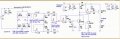
I have built the complete V2I converter on a bread board, it works OK. [no modifications to the posted circuit]
Vin=0v Iout=4mA
Vin=4v Iout = 20mA

Uses a 250R Load resistor.
20k resistor in the FET source.

Vcc =24Vdc, Vload[drive] 15Vdc

LM358 OPA.

Please post a clear photo image of your built circuit, so I can help you find the problem.

Eric
 

Thread Starter

rajitpk

Joined Jan 30, 2018
108
hi rijat,
Update:
I have built the complete V2I converter on a bread board, it works OK. [no modifications to the posted circuit]
Vin=0v Iout=4mA
Vin=4v Iout = 20mA

Uses a 250R Load resistor.
20k resistor in the FET source.

Vcc =24Vdc, Vload[drive] 15Vdc

LM358 OPA.

Please post a clear photo image of your built circuit, so I can help you find the problem.

Eric
dear eric,

i found the problem where it is.
actually i already assemble my circuit( amplifier and v-i converter alone) on PCB board. after that only i added JFET and zener diode as externally thru wire.

yesterday i checked the 4mA condition by disconnecting the bridge output alone. there is some problem.
when my circuit is opened(when disconnect the bridge output from the amplifier circuit) output at the amplifier generate 0.65V itself. so that why i am getting those(near 7.56 mA) result.

today i check the circuit by balancing the bridge and get the amplifier output close to 0.03 at that time i can able to get the 4 mA .
and get as well as the maximum condition but i get 21 mA as a clamped output instant of 20mA.
 

ericgibbs

Joined Jan 29, 2010
21,625
hi rajit,
Pleased to hear you have found the problem.
Clamping at 21mA, IMO is as close as you will get with that circuit.
Why is it so important to clamp at 20mA.?
Never run the project with the bridge disconnected.
E
 

Thread Starter

rajitpk

Joined Jan 30, 2018
108
hi rajit,
Pleased to hear you have found the problem.
Clamping at 21mA, IMO is as close as you will get with that circuit.
Why is it so important to clamp at 20mA.?
Never run the project with the bridge disconnected.
E
dear eric,
yes i should clamped the output at 20mA. ( because i will give it as an input to the PLC).
and also is it possible to get 20mA output when the amplifier output is 5V.

you said, Never run the project with the bridge disconnected.
may i know why not check the zero signal condition by disconnecting the bridge. does it not mean giving zero signal to the amplifier.
 
Top