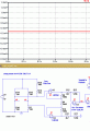
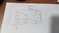
how to get the stable amplified output for strain gauge

ericgibbs

Joined Jan 29, 2010
21,622
hi,
Could you post the PLC datasheet, so that I can check what maximum input mA current it will accept.?
You could modify the circuit to give 20mA with a Vin of 5V, but why would you want to do that.?

When the amplifier inputs to the bridge are disconnected, 'floating' the Vout will be indeterminate, ie: either fluctuating or saturated.

E
 

Thread Starter

rajitpk

Joined Jan 30, 2018
108
hi,
Could you post the PLC datasheet, so that I can check what maximum input mA current it will accept.?
You could modify the circuit to give 20mA with a Vin of 5V, but why would you want to do that.?

When the amplifier inputs to the bridge are disconnected, 'floating' the Vout will be indeterminate, ie: either fluctuating or saturated.

E
yes eric because i have give it to 4-20mA to the AI card of the plc for testing
so i should convert 0-5 V amplifier is convert in to 4-20mA. so thats why i asked
 

ericgibbs

Joined Jan 29, 2010
21,622
hi rajit,
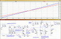
For Vout = 5v at 303.07R
Change
R9 Gain to 3k65
R2 Q1 Emitter to 12k4
R6 FET Source to 27k
IN750 to 5v6 Zener.

Its important that you decide and finalise a specification for this project.

E
Added modified circuit.
 

Attachments

Last edited:

Thread Starter

rajitpk

Joined Jan 30, 2018
108
hi rajit,
For Vout = 5v at 303.07R
Change
R9 Gain to 3k65
R2 Q1 Emitter to 12k4
R6 FET Source to 27k
IN750 to 5v6 Zener.

Its important that you decide and finalise a specification for this project.

E
Added modified circuit.
okay eric. i will test it and post my reply.
still now i work on my circuit for getting proper output with in my availability. so i will work until i get proper output

i have an confusion.Kindly, could you briefly explain the v-i conversion how the 5 volt convert as 20mA range based on the selection of resistance and how JFET has influence to modify the output 4mA at zero signal
 

ericgibbs

Joined Jan 29, 2010
21,622
hi rajit,
Read this AAC Worksheet link for V2I operation.
https://www.allaboutcircuits.com/te.../chpt-8/voltage-to-current-signal-conversion/

The FET is configured as a Constant Current source [CC] , the current is set by the Source resistance.
This current flows thru the Q1 Collector resistor in 'parallel' with the current from U3/Q1 output and causes an additional voltage drop across the Collector resistor.
The CC is chosen so that 4mA flows in Q2 Collector when Vout from the 1st stage amplifier is 0V.

Do you follow OK.
BTW: is this a College assignment.?

Eric
 

Thread Starter

rajitpk

Joined Jan 30, 2018
108
hi rajit,
Read this AAC Worksheet link for V2I operation.
https://www.allaboutcircuits.com/te.../chpt-8/voltage-to-current-signal-conversion/

The FET is configured as a Constant Current source [CC] , the current is set by the Source resistance.
This current flows thru the Q1 Collector resistor in 'parallel' with the current from U3/Q1 output and causes an additional voltage drop across the Collector resistor.
The CC is chosen so that 4mA flows in Q2 Collector when Vout from the 1st stage amplifier is 0V.

Do you follow OK.
BTW: is this a College assignment.?

Eric
yes eric i can follow. i will go thru the work sheet.
its my internship project.
thanks a lot for your guidance... its mean lots for me....:)

i will test and post my readings.

thanks,
R
 

Thread Starter

rajitpk

Joined Jan 30, 2018
108
hi rajit,
For Vout = 5v at 303.07R
Change
R9 Gain to 3k65
R2 Q1 Emitter to 12k4
R6 FET Source to 27k
IN750 to 5v6 Zener.

Its important that you decide and finalise a specification for this project.

E
Added modified circuit.
dear eric,
i can get the 4-20mA for 0-5 V amplified output using 5.6V zener diode.
sorry for the late reply.

if i have to provide option for span and zero adjustment in the circuit, the span adjustment can make by adjusting the R9 resistance. but where can we make zero adjustment for the amplifier circuit and what is the purpose for the zero(offset)adjustment in the amplifier side alone.
Note:
i assemble amplifier and v-i converter circuit alone in the PCB board. i give the mv (bridge input) as an input from externally.
 

ericgibbs

Joined Jan 29, 2010
21,622
hi rajit.
Most bridges, especially DIY versions will not give 0.00mV out, Off Load, so a Zero or Null circuit is required.
This can achieved by adding a high value trim resistor in parallel with one of the bridge arm resistors
or
by injecting an Offset voltage into either the +INP or -INP of the OPA.
This is usually a high value fixed resistor in series with a Zero trim pot, connected in series from the +Vbridge supply and the to either +INP or -INP.

Do you follow that OK.?
What is the Bridge output and the amp Vout with no load on the bridge.??

E
 

Thread Starter

rajitpk

Joined Jan 30, 2018
108
hi rajit.
Most bridges, especially DIY versions will not give 0.00mV out, Off Load, so a Zero or Null circuit is required.
This can achieved by adding a high value trim resistor in parallel with one of the bridge arm resistors
or
by injecting an Offset voltage into either the +INP or -INP of the OPA.
This is usually a high value fixed resistor in series with a Zero trim pot, connected in series from the +Vbridge supply and the to either +INP or -INP.

Do you follow that OK.?
What is the Bridge output and the amp Vout with no load on the bridge.??

E
in my circuit, for 0 mv (no load) input, 78mV is the amplifier output.
my doubt is the zero adjustment is needed , if we add the bridge setup with the amplifier circuit.

now just assume, the mv input is generated from load cell, so my amplifier circuit have to amplify the signal from load pin and convert it to 4-20mA output. so in kind of application, where i can add the provision of zero adjustment
 

ericgibbs

Joined Jan 29, 2010
21,622
hi,
That would be the 2nd option.
by injecting an Offset voltage into either the +INP or -INP of the OPA.
This is usually a high value fixed resistor in series with a Zero trim pot, connected in series from the +Vbridge supply and the to either +INP or -INP.


ie: at the input of the OPA

I assume the 78mV is a positive voltage.? I will do some sums and repost.
E


Thread Starter

rajitpk

Joined Jan 30, 2018
108
hi,
That would be the 2nd option.
by injecting an Offset voltage into either the +INP or -INP of the OPA.
This is usually a high value fixed resistor in series with a Zero trim pot, connected in series from the +Vbridge supply and the to either +INP or -INP.


ie: at the input of the OPA

I assume the 78mV is a positive voltage.? I will do some sums and repost.
E
yes eric it is positive output signal.or 0 V input, the amplifer output is 78mV.
 

Thread Starter

rajitpk

Joined Jan 30, 2018
108
hi,
Look at this Zero trim circuit.
Without it the Vout is ~48mV, with it ~ 200uV.
Experiment with the 'best' values to suit your bridge.
E
dear eric,
i will test that circuit.
but my doubts is, the zero adjustment is need for all kind of application, whether the inputs from bridge or loadcell or any analog variation?
 

ericgibbs

Joined Jan 29, 2010
21,622
hi,
On almost all low level circuits, ie: in the uV or mV analog levels, they will require some method nulling out any voltage offset from the sensors and OPA's.
As you can imagine it is very expensive and almost impossible to manufacture electronic components that have zero tolerances in their values.

Is this what you are asking.?
E
 

Thread Starter

rajitpk

Joined Jan 30, 2018
108
hi,
Look at this Zero trim circuit.
Without it the Vout is ~48mV, with it ~ 200uV.
Experiment with the 'best' values to suit your bridge.
E
dear eric,
i worked the circuit. but i doesn't change. in my circuit 78mV after add the circuit it varies 76mV.
there is no big changes
 

ericgibbs

Joined Jan 29, 2010
21,622
hi rajit,
Please post your circuit showing the zero components and connections that you are trying.
The circuit I suggested is very often used to balance out any offset signal, it should be working.
E
 

Thread Starter

rajitpk

Joined Jan 30, 2018
108
hi rajit,
Please post your circuit showing the zero components and connections that you are trying.
The circuit I suggested is very often used to balance out any offset signal, it should be working.
E
now i test with the bridge circuit eric, i will post my circuit
 

Thread Starter

rajitpk

Joined Jan 30, 2018
108
hi rajit,
Please post your circuit showing the zero components and connections that you are trying.
The circuit I suggested is very often used to balance out any offset signal, it should be working.
E
dear eric,
please find the attachment for the circuit connection for zero adjustment.
before adding the adjustment circuit, the readings is,
for 0mV - 78mV will be my amplifier output

after that i didn't make any change in bridge resistance just add the zero adjustment circuit,
then, bridge output varies from 0mv to (-9.4mV) and amplifier output varies from 78mV to 87mV.

i test with 120k instant of 47k, the reading is
bridge output varies from 0mv to (-4.1 mV) and amplifier output varies from 78mV to 82 mV.

the amplifier output get increased while adding the zero adjustment circuit.
 

Attachments

ericgibbs

Joined Jan 29, 2010
21,622
hi rajit,
From your description, if increasing the Offset voltage increases the Vout, it means the Offset should be changed to connect to the Va terminal of the bridge.
Try it and post what you measure, the Voffset should work.

E
 

Thread Starter

rajitpk

Joined Jan 30, 2018
108
da
hi rajit,
From your description, if increasing the Offset voltage increases the Vout, it means the Offset should be changed to connect to the Va terminal of the bridge.
Try it and post what you measure, the Voffset should work.
i also try it with -V with Va and Vb. the same thing gets repeat whether bridge output increase +ve or -ve

E
dear eric,

i test the circuit connecting with Va. but this time bridge output varies positive which lead high variation in amplifier. the reading is for connecting 47 k with Va,
bridge output varies from 0mv to (8.4 mV) and amplifier output varies from 78mV to 20.1V

the zero adjustment affect the bridge output based on that amplifier output is varied.
didn't happen any off set process.
 
Top