NE555 Monostable: OUT stuck HIGH after power cycle — fixed by oscilloscope probe contact

Thread Starter

kimsunghwan

Joined Sep 18, 2026
10
Hi everyone,

I'm having an intermittent issue with a NE555 (NA555D, SOIC-8) monostable circuit on a finished PCB. Looking for help.

Circuit specs:

  • VCC = 12V
  • R57 = 1MΩ (timing resistor, Pin7-Pin8)
  • C45 = 10μF / 25V / X7R / 3225 (timing capacitor, Pin6-GND)
  • C38 = 100nF / 25V / 1608 (VCC decoupling, Pin8-GND)
  • C43 = 10nF / 25V / 1608 (Pin5-GND)
  • Pin4 (RESET) = tied directly to +12V
  • Trigger source: NPN transistor (Q7, BC846BL) driving Pin2
  • Designed timing: t = 1.1 × 1MΩ × 10μF ≈ 11s
Symptoms:

  1. PCB was working normally in the field
  2. After a power cycle (OFF → ON), TRIG (Pin2) is HIGH and OUT (Pin3) is also stuck HIGH
  3. Power cycling multiple times does not recover the circuit — same stuck condition every time
  4. While measuring pins 2, 3, 4, 5, 6 with an oscilloscope probe, the circuit spontaneously recovers to normal operation at some point during measurement
Any help would be greatly appreciated. Thank you.
 

Attachments

crutschow

Joined Mar 14, 2008
38,938
Does it not recover after >11s?

What is the voltage at pin 7 (THRES) when the output is stuck high?

Do you want to add a power-on reset?
One way is to connect the C45 timing capacitor to V+ instead of ground will generally make the output low on power up.
 
Last edited:

MrChips

Joined Oct 2, 2009
35,296
Timing resistor 1MΩ is too high.
Your oscilloscope input impedance is 1MΩ and will affect the operation of the circuit.
Even if you use a probe with 10MΩ input impedance, it can affect the circuit.
The solution is to reduce the value of the timing resistor and increase the value of the timing capacitor by the same ratio.
 

AlbertHall

Joined Jun 4, 2014
12,663
When the trigger pin (Pin 2) of an NE555 timer is held constantly low (below 1/3 of the supply voltage, \(V_{CC}\)), the timer enters a latched state where the output (Pin 3) stays high indefinitely, and the internal discharge transistor (Pin 7) stays open.

Is the MCU keeping the transistor turned on?
 

Thread Starter

kimsunghwan

Joined Sep 18, 2026
10
Does it not recover after >11s?

What is the voltage at pin 7 (THRES) when the output is stuck high?

Do you want to add a power-on reset?
One way is to connect the C45 timing capacitor to V+ instead of ground will generally make the output low on power up.
When I was checking the pins with the oscilloscope probe, at some point the OUT (Pin3) spontaneously recovered to LOW (normal state). I wasn't able to measure Pin7 at that exact moment. I will try to reproduce the fault condition and measure Pin7 voltage again. Will report back.

To clarify — in normal operation, the circuit works correctly immediately from power-up. However, in the fault condition, OUT was stuck HIGH immediately from power-up. I was not able to confirm whether it would eventually recover after 11 seconds.

Also, I will try your suggestion of connecting C45 to V+ instead of GND. Could you explain how connecting C45 to V+ affects the monostable timing operation? Does the timing formula t = 1.1 × R × C still hold in that configuration?

Additionally, I've been researching possible solutions and found two options: (1) adding a bypass capacitor in parallel on Pin8 (VCC), and (2) adding an RC delay circuit on Pin4 (RESET) with a discharge diode. What do you think about these approaches?
 

Attachments

Thread Starter

kimsunghwan

Joined Sep 18, 2026
10
Timing resistor 1MΩ is too high.
Your oscilloscope input impedance is 1MΩ and will affect the operation of the circuit.
Even if you use a probe with 10MΩ input impedance, it can affect the circuit.
The solution is to reduce the value of the timing resistor and increase the value of the timing capacitor by the same ratio.

Understood. I will look into reducing the timing resistor value and increasing the timing capacitor value proportionally to maintain the same timing interval. Do you have a recommended value for the timing resistor in this case?


Additionally, I've been researching possible solutions and found two options: (1) adding a bypass capacitor in parallel on Pin8 (VCC), and (2) adding an RC delay circuit on Pin4 (RESET) with a discharge diode. What do you think about these approaches?
 

Attachments

Thread Starter

kimsunghwan

Joined Sep 18, 2026
10
When the trigger pin (Pin 2) of an NE555 timer is held constantly low (below 1/3 of the supply voltage, \(V_{CC}\)), the timer enters a latched state where the output (Pin 3) stays high indefinitely, and the internal discharge transistor (Pin 7) stays open.

Is the MCU keeping the transistor turned on?


Good point. When the product powers on, TRIG (Pin2) should be HIGH because the MCU GPIO is LOW (transistor Q7 is OFF). Therefore OUT (Pin3) should be LOW in normal standby state. However, in the fault condition, OUT was stuck HIGH even though TRIG was HIGH. This is what makes this case puzzling.


Additionally, I've been researching possible solutions and found two options: (1) adding a bypass capacitor in parallel on Pin8 (VCC), and (2) adding an RC delay circuit on Pin4 (RESET) with a discharge diode. What do you think about these approaches?
 

Attachments

crutschow

Joined Mar 14, 2008
38,938
I was not able to confirm whether it would eventually recover after 11 seconds.
Why is that?
Could you explain how connecting C45 to V+ affects the monostable timing operation? Does the timing formula t = 1.1 × R × C still hold in that configuration?
It has no effect on the normal timing period as V+ is AC ground to the capacitor.
The only effect is that the THRES pin will go high as the power comes on, which should reset the output to low.

Note that you need to observe the capacitor polarity and connect the positive lead to V+ if you do that.
Additionally, I've been researching possible solutions and found two options: (1) adding a bypass capacitor in parallel on Pin8 (VCC), and (2) adding an RC delay circuit on Pin4 (RESET) with a discharge diode.
1 is just good standard practice for any IC, but I don't think it will affect your power-on problem.

2 should work to give a power-on reset if changing C45 doesn't work.
 

Thread Starter

kimsunghwan

Joined Sep 18, 2026
10
Why is that?
It has no effect on the normal timing period as V+ is AC ground to the capacitor.
The only effect is that the THRES pin will go high as the power comes on, which should reset the output to low.

Note that you need to observe the capacitor polarity and connect the positive lead to V+ if you do that.
1 is just good standard practice for any IC, but I don't think it will affect your power-on problem.

2 should work to give a power-on reset if changing C45 doesn't work.
I was on vacation at the time, and my colleague first observed the fault. While measuring with an oscilloscope probe, the circuit suddenly started working normally on its own. So we couldn't capture the exact fault behavior. What we know for certain is: normally after power-up, OUT should go LOW, but instead it stayed HIGH — which caused the 3.3V/5V control power to shut down.


Regarding your suggestion to connect C45 to V+: could you recommend what type of capacitor would be best for this configuration? Since the positive lead needs to connect to V+, a polarized cap would be required. Would an electrolytic or tantalum capacitor be appropriate, or is there another type you'd recommend?
 

crutschow

Joined Mar 14, 2008
38,938
What we know for certain is: normally after power-up, OUT should go LOW, but instead it stayed HIGH
How do you know that for certain?
There is nothing in the design to guarantee which way it powers up.
Regarding your suggestion to connect C45 to V+: could you recommend what type of capacitor would be best for this configuration?
The 10μF / 25V / X7R / 3225 capacitor listed in your parts list.
I was thinking you were using a polarized capacitor, but that capacitor is non-polarized ceramic type so you can connect it either way.
 

Thread Starter

kimsunghwan

Joined Sep 18, 2026
10
How do you know that for certain?
There is nothing in the design to guarantee which way it powers up.
The 10μF / 25V / X7R / 3225 capacitor listed in your parts list.
I was thinking you were using a polarized capacitor, but that capacitor is non-polarized ceramic type so you can connect it either way.

Thank you for the clear explanation and confirmation!
I now understand that the power-up state isn't guaranteed by default due to the internal latch behavior and noise. I am going to try the solutions you suggested—especially placing that 10μF X7R ceramic capacitor as close to the power pins as possible to stabilize the supply.
I'll test these out and update you with the results soon. Thanks again for your help!
 

Thread Starter

kimsunghwan

Joined Sep 18, 2026
10
How do you know that for certain?
There is nothing in the design to guarantee which way it powers up.
The 10μF / 25V / X7R / 3225 capacitor listed in your parts list.
I was thinking you were using a polarized capacitor, but that capacitor is non-polarized ceramic type so you can connect it either way.
AN170 warned against ceramic disc capacitors in the timing network. But I think modern X7R MLCC is significantly better than the ceramic disc capacitors of that era. Do you still recommend switching to tantalum?
 

Attachments

crutschow

Joined Mar 14, 2008
38,938
AN170 warned against ceramic disc capacitors in the timing network. But I think modern X7R MLCC is significantly better than the ceramic disc capacitors of that era. Do you still recommend switching to tantalum?
No, I never recommended that.
That ceramic should be fine.
It's advantage is lower leakage than tantalum.
 

crutschow

Joined Mar 14, 2008
38,938
I am going to try the solutions you suggested—especially placing that 10μF X7R ceramic capacitor as close to the power pins as possible to stabilize the supply.
Connecting C45 to the V+ is not for stabilizing the supply, it's so that pin 6 comes up with the V+ voltage during power-on, which should set the output low.

But be sure you have a 100nF capacitor from pin 8 to ground for decoupling.
 

Thread Starter

kimsunghwan

Joined Sep 18, 2026
10
Connecting C45 to the V+ is not for stabilizing the supply, it's so that pin 6 comes up with the V+ voltage during power-on, which should set the output low.

But be sure you have a 100nF capacitor from pin 8 to ground for decoupling.
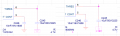
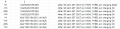
I tested your suggestion (connecting C45 positive to V+) with various R and C combinations. Results below:

1789997103665.png

1789997035754.png


Why does 1M + 10μF X7R fail, but 1M + 40μF X5R pass? The resistor is the same, so charging current should be identical. What is causing this difference?


Since 1M + 10μF X7R failed even with your suggested fix, we are considering going with the 40μF (4x10μF X5R) combination instead. Is this the right direction, or do you have a better recommendation?
 

crutschow

Joined Mar 14, 2008
38,938
Why does 1M + 10μF X7R fail, but 1M + 40μF X5R pass?
It likely has to do with how fast the V+ voltage rises when activated.
A 40µF will stay high longer than a 10µF capacitor, making it more likely to reset the output.

To guarantee an output low at startup, you should use the RC circuit that holds the Reset pin low (<0.7V) during power-up.
But the 100k/10µF reset circuit shown in post #8 will only hold the reset below that voltage for about 60ms, which may not be enough, depending upon how fast the power-up occurs.

You can increase that Reset time to near 1s by adding a 1 Megohm resistor and changing the circuit as shown below:
The reset voltage only needs to be above 0.7V for no reset (Reset inhibited).

1790025635752.png
 
Last edited:

Thread Starter

kimsunghwan

Joined Sep 18, 2026
10
It likely has to do with how fast the V+ voltage rises when activated.
A 40µF will stay high longer than a 10µF capacitor, making it more likely to reset the output.

To guarantee an output low at startup, you should use the RC circuit that holds the Reset pin low (<0.7V) during power-up.
But the 100k/10µF reset circuit shown in post #8 will only hold the reset below that voltage for about 60ms, which may not be enough, depending upon how fast the power-up occurs.

You can increase that Reset time to near 1s by adding a 1 Megohm resistor and changing the circuit as shown below:
The reset voltage only needs to be above 0.7V for no reset (Reset inhibited).

View attachment 371582
So to summarize your latest suggestion: revert C45 (DISCH pin capacitor) back to GND, and instead add an RC delay circuit on the Reset pin to guarantee a reset at power-up. Is that correct?
Also, this RC circuit holds the Reset pin below 0.7V for about 1 second, forcing the 555 to reset during power-up. And since there is a pull-down path, a discharge diode is not needed — is that right?
 

crutschow

Joined Mar 14, 2008
38,938
So to summarize your latest suggestion: revert C45 (DISCH pin capacitor) back to GND, and instead add an RC delay circuit on the Reset pin to guarantee a reset at power-up. Is that correct?
Also, this RC circuit holds the Reset pin below 0.7V for about 1 second, forcing the 555 to reset during power-up. And since there is a pull-down path, a discharge diode is not needed — is that right?
Yes to both.
Without the diode it will take a few seconds for the Reset function to recover before restart, but I assumed that would not be a problem.
If you do need to add a diode for fast reset, use a small Schottky type such as the BAT54.
 
Last edited:

Thread Starter

kimsunghwan

Joined Sep 18, 2026
10
Yes to both.
Without the diode it will take a few seconds for the Reset function to recover before restart, but I assumed that would not be a problem.
If you do need to add a diode for fast reset, use a small Schottky type such as the BAT54.

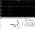
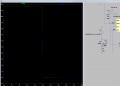
I simulated the RC delay circuit (R9=1MΩ, C5=10μF, D2=BAT54) on the Reset pin.


Without connecting to the Reset pin: the RC charges slowly as expected — clear delay visible.
With Reset pin connected: voltage jumps HIGH immediately — RC delay is almost completely lost.


It appears the 555's internal Reset pin pulls up C5 too fast, making the RC delay ineffective.
Is the RC approach on the Reset pin not viable for the NE555? Is there another method we should consider?


1790042690620.png
1790043061098.png
 
Top