 Facebook
 Google
 GitHub
 Linkedin
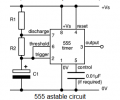
I wired the NE555 timer as an astable multi vibrator and have this output, is this the best I can expect as a square wave from this chip, or is there a fault? I have checked the calibration of my probe and it's fine.
NE555 timer issue?
- Thread starter Homebrew1964
- Start date
| Thread starter | Similar threads | Forum | Replies | Date |
|---|---|---|---|---|
|
|
NE555 timer pin5 | Digital Design | 13 | |
| P | LTspice - NE555 Timer Not Resetting Properly | PCB Layout , EDA & Simulations | 11 | |
|
|
555 Timer with Passive Transducer | Homework Help | 13 | |
|
|
NE555 timer reset pin issue | Digital Design | 1 | |
|
|
Reset an NE555 timer at a specific point | PCB Layout , EDA & Simulations | 6 |


