Facebook
 Google
 GitHub
 Linkedin


While thinking about a problem from another post, I had a small "Eureka" moment, and came up with a relatively simple design for a bench-type, constant-voltage/constant-current power supply circuit that allows independent adjustment of both voltage and current from zero to max.
This makes it particularly useful for things like charging various battery types, sizes, and voltages, most of which require a CC/CV charging profile.
Not sure how unique it is, but generally circuits with both fully adjustable voltage and current tend to be more complex, and I don't see how this could be made much simpler, so I thought I'd post it for anyone interested (below).
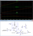
It uses a Sziklai-pair buffered Howland current-pump circuit for the CC function (U1-A), and an op amp (U1-B) driving the Sziklai-pair as emitter-follower circuit for the CV function.
D1 allows the CV circuit to take control when the current is below the current setpoint.
It has a low drop-out voltage of about 1V.
The voltage and current control are both referenced to ground from the TL431, 2.5V reference.
The ground reference means they both could also be readily controlled from the DAC output of a micro in place of the pots.
The circuit below is configured for a maximum output of 15V and 2A current from a 16V supply.
The sim below shows the output voltage and current for current settings of 0, 1A, and 2A, with a voltage setting of 7.5V.
Note how it goes from CC mode to CV mode as the output load goes from 1 to 11 ohms.
The op amps do need to be rail-rail types.
For more detail on the design, I posted a description here.
This makes it particularly useful for things like charging various battery types, sizes, and voltages, most of which require a CC/CV charging profile.
Not sure how unique it is, but generally circuits with both fully adjustable voltage and current tend to be more complex, and I don't see how this could be made much simpler, so I thought I'd post it for anyone interested (below).
It uses a Sziklai-pair buffered Howland current-pump circuit for the CC function (U1-A), and an op amp (U1-B) driving the Sziklai-pair as emitter-follower circuit for the CV function.
D1 allows the CV circuit to take control when the current is below the current setpoint.
It has a low drop-out voltage of about 1V.
The voltage and current control are both referenced to ground from the TL431, 2.5V reference.
The ground reference means they both could also be readily controlled from the DAC output of a micro in place of the pots.
The circuit below is configured for a maximum output of 15V and 2A current from a 16V supply.
The sim below shows the output voltage and current for current settings of 0, 1A, and 2A, with a voltage setting of 7.5V.
Note how it goes from CC mode to CV mode as the output load goes from 1 to 11 ohms.
The op amps do need to be rail-rail types.
For more detail on the design, I posted a description here.
Last edited: