how to get the stable amplified output for strain gauge

Thread Starter

rajitpk

Joined Jan 30, 2018
108
OK,
when its working post back your test measurements and we can compare the results using a LTSpice simulation.
E
hi eric,

i test my circuit what i post #29 using LM 358. ( also i use instead of n-MOSFET i use CL100 transistor and for p-MOSFET i use CK100 )
in my 4-20mA converter circuit for 1.1 v input i get 31mA
and for 4.4v i get 45mA as a output.
this kind of situation what to do? to get a 4-20mA for my input...
is that any components need to change
 

Thread Starter

rajitpk

Joined Jan 30, 2018
108
hi rajit,
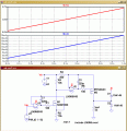
This is a LTSpice sim of your circuit using MOSFET's, in order to prove the basic design.
It works OK.
I will now look at making your transistor modifications.
E
yes i have to modify for the transistor. because i cannot able to get even datasheet for p-MOSFET.
 

ericgibbs

Joined Jan 29, 2010
21,642
hi,
The CL and CK are general purpose medium power transistors.
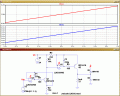
In the attached LTS image, I have tried a lot of various types of general purpose transistors and they all work OK.
Have you changed anything else in the circuit.?
E
 

Attachments

Thread Starter

rajitpk

Joined Jan 30, 2018
108
hi,
The CL and CK are general purpose medium power transistors.
In the attached LTS image, I have tried a lot of various types of general purpose transistors and they all work OK.
Have you changed anything else in the circuit.?
E
no eric. i only modify the mosfet and op-amp.
but practically i cannot get the output
 
Last edited:

ericgibbs

Joined Jan 29, 2010
21,642
hi,
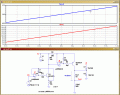
Tried more transistors, works OK.
Check the value of R1 and R2 on the original circuit, they should be 10K's
Only by changing these values can I make the circuit give the results you are getting.

Also is it possible that you could post a clear photo of the project.?
E
 

Thread Starter

rajitpk

Joined Jan 30, 2018
108
hi,
Tried more transistors, works OK.
Check the value of R1 and R2 on the original circuit, they should be 10K's
Only by changing these values can I make the circuit give the results you are getting.

Also is it possible that you could post a clear photo of the project.?
E
of course i will post..
my project is simple... i have to give wheat stone bridge output variation to PLC as a 4-20mA. for that first amplify the mV to V then i convert my V to mA for PLC input
 

Thread Starter

rajitpk

Joined Jan 30, 2018
108
hi,
The CL and CK are general purpose medium power transistors.
In the attached LTS image, I have tried a lot of various types of general purpose transistors and they all work OK.
Have you changed anything else in the circuit.?
E
where did you check the I out before 22 ohm resistor or after ? here i have little confusion.. always we have to check the current measurement before the load(ex.22 ohm resistor)
 

ericgibbs

Joined Jan 29, 2010
21,642
hi,
Checking the d/s for the LM358, it is possible that the OPA input range is outside its permitted operating limit, when being used in this circuit.?
Check the LM358 datasheet.
E
 

ericgibbs

Joined Jan 29, 2010
21,642
hi,
Checking the LM358 datasheet indicates that the Input voltage range for that OPA is being exceeded, when used in that circuit.
The recommended OPA is a LT1490 which is specified to work with inputs upto the Vss supply voltage.
E

EDIT:
Do you have a 15V or 12V voltage regulator in your component stock.???
or some diodes.? eg; 1N400x types.
 

Attachments

Last edited:

Thread Starter

rajitpk

Joined Jan 30, 2018
108
hi,
Checking the LM358 datasheet indicates that the Input voltage range for that OPA is being exceeded, when used in that circuit.
The recommended OPA is a LT1490 which is specified to work with inputs upto the Vss supply voltage.
E

EDIT:
Do you have a 15V or 12V voltage regulator in your component stock.???
or some diodes.? eg; 1N400x types.
yes i have both voltage regulator and can get the diodes
 

ericgibbs

Joined Jan 29, 2010
21,642
hi,
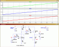
This shows a LM324 supply at 24V and the Rshunt supply at 15V, this ensures that the high side shunt voltage input to the LM324 falls within the limits stated by the LM324 datasheet.
It states Vsupply -1.5V

It is an option I would try, the alternative is to get LT1490 OPA's
E
 

Attachments

Thread Starter

rajitpk

Joined Jan 30, 2018
108
hi,
This shows a LM324 supply at 24V and the Rshunt supply at 15V, this ensures that the high side shunt voltage input to the LM324 falls within the limits stated by the LM324 datasheet.
It states Vsupply -1.5V

It is an option I would try, the alternative is to get LT1490 OPA's
E
hi,
okay i will check using 15 V at Rshunt and post my reading
 

Thread Starter

rajitpk

Joined Jan 30, 2018
108
hi,
This shows a LM324 supply at 24V and the Rshunt supply at 15V, this ensures that the high side shunt voltage input to the LM324 falls within the limits stated by the LM324 datasheet.
It states Vsupply -1.5V

It is an option I would try, the alternative is to get LT1490 OPA's
E
ERIC,
may i know why you ignore the 1 micro farad capacitor at Rshunt side.. is that any purpose..?
 

ericgibbs

Joined Jan 29, 2010
21,642
hi r,
That 1uF is part of the power supply decoupling, it should be on your actual circuit build, the LTSpice sim does not require it to work.
E
 
Top