hi eric,
i tested with 15v for Rshunt... by this i get 59mA for 4.4 V
then i reduced to 13 V and change the R load to 270 ohm... then i get 20.26 mA for 4.4 V and 12 mA for 1.3 V.
is the way is correct...?
hi rajit,
The circuit I posted should work OK, have you changed any other component values.
Can you post a clear photo of the circuit, so that I can check the build.?
Eric
EDIT:
I have tried many modifications to the circuit and I cannot get the results that you measure.
Check your 24V power rail and Rshunt supply connections.
UPDATE:
I assume that your 15V regulated supply to the Rshunt input is decoupled, also the 24V is decoupled.?
The 24V must only power the LM358's and the 15V for the Rshunt, only the shunt circuit.
Also the 24V and 15V Common 0v lines must be connected together.
hi rajit,
The circuit I posted should work OK, have you changed any other component values.
Can you post a clear photo of the circuit, so that I can check the build.?
Eric
EDIT:
I have tried many modifications to the circuit and I cannot get the results that you measure.
Check your 24V power rail and Rshunt supply connections.
UPDATE:
I assume that your 15V regulated supply to the Rshunt input is decoupled, also the 24V is decoupled.?
The 24V must only power the LM358's and the 15V for the Rshunt, only the shunt circuit.
Also the 24V and 15V Common 0v lines must be connected together.
hi rajit,
The diagram is clear, OK.
This is a puzzling problem, it is a simple circuit that I have built and used in the past with no problems.???
What current output do you get for 0V input.?, it should be zero.
I will look further into your results.
Eric
EDIT:
Posted my LTSpice asc sim file, in case some other member wishes to run it.
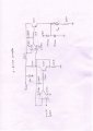
sorry eric.. i made mistake while drawing the circuit for my post...
but practically i work correct one.. i connect the ck100 emitter terminal to power supply and collector to the diode side.
again i will work on the circuit.. with bc 547 and bc 557 with 15v Rshunt and i will post my reading...
thanks for your support....
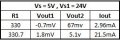
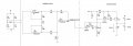
here i post my final circuit and readings...
my requirement is at balanced condition of the bri dge i sholud get the Iout 4 mA... at R1 = 330.7 my output should be 20mA...
as per my output i have to improve Iout at balanced condition...
can you review my circuit...?
and also i should use 5V or 24V as a power supply..( as per comments)
hi rijat,
I will look thru your circuit diagram. [will post back more info later]
As you are using LM358, they must have a higher supply voltage than the Rshunt voltage supply.
The LM358 is not specified to work with input voltages equal to its supply voltage.
So the Rshunt supply is 15Vreg.
Ideally the R15 resistor should be 250R, so that a 4mA current will produce a voltage drop of 1v and 20mA a 5V drop.
These voltage drops are compared with 1V thru 5V voltages being input from the bridge circuit, so that the output transistor Q2 outputs 4mA thru 20mA.
What is your bridge supply voltage and also what is the supply voltage to the LM358's in the bridge amp.?
hi rijat,
I will look thru your circuit diagram. [will post back more info later]
As you are using LM358, they must have a higher supply voltage than the Rshunt voltage supply.
The LM358 is not specified to work with input voltages equal to its supply voltage.
So the Rshunt supply is 15Vreg.
Ideally the R15 resistor should be 250R, so that a 4mA current will produce a voltage drop of 1v and 20mA a 5V drop.
These voltage drops are compared with 1V thru 5V voltages being input from the bridge circuit, so that the output transistor Q2 outputs 4mA thru 20mA.
What is your bridge supply voltage and also what is the supply voltage to the LM358's in the bridge amp.?
hi rijat,
I will look thru your circuit diagram. [will post back more info later]
As you are using LM358, they must have a higher supply voltage than the Rshunt voltage supply.
The LM358 is not specified to work with input voltages equal to its supply voltage.
So the Rshunt supply is 15Vreg.
Ideally the R15 resistor should be 250R, so that a 4mA current will produce a voltage drop of 1v and 20mA a 5V drop.
These voltage drops are compared with 1V thru 5V voltages being input from the bridge circuit, so that the output transistor Q2 outputs 4mA thru 20mA.
What is your bridge supply voltage and also what is the supply voltage to the LM358's in the bridge amp.?
hi r,
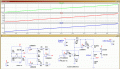
I have run your circuit in LTSpice simulation, it works as expected.
I have set the Gain of the bridge amp to 1000, so 5mV from the bridge gives a Vout of 5V.
Inputting 0v to 5V to the V2I converter circuit gives 0mA thru 20mA.
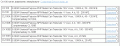
Check thru the attached circuit.
E
hi r,
I have run your circuit in LTSpice simulation, it works as expected.
I have set the Gain of the bridge amp to 1000, so 5mV from the bridge gives a Vout of 5V.
Inputting 0v to 5V to the V2I converter circuit gives 0mA thru 20mA.
Check thru the attached circuit.
E

 Facebook
 Google
 GitHub
 Linkedin