Facebook
 Google
 GitHub
 Linkedin
I have to go do some things soon, so I'll leave this here now.
The output of a bridge is directly proportional to the excitation voltage. If the bridge is perfectly balanced there will be no differential signal out, regardless of the excitation voltage. As soon as the bridge becomes unbalanced, then the effect of proportionality can be seen readily. If the excitation is not stable and free of noise the output of the bridge cannot be stable and free of noise.
If the output of the amplifier on the bridge is going to the input of an analog to digital converter that gets its voltage reference from exactly the same place as the bridge excitation, the variation in bridge output due to variation in the excitation voltage is cancelled. But in practice this will rarely happen.
The impression I get is that Arduino and other hobby boards typically just use the 5 V supply, perhaps with some filtering, as the reference for the ADC (some microcontrollers with ADCs have the option of an external ref, some have a reasonably good internal ref, some give no choice but to use the digital V+ as a ref). That's OK if the circuit is done very carefully and the demands are not high. If the 5 V used comes form a computer's USB port, it will be horrible. It will vary by hundreds of millivolts and have all sorts of noise on it. It is generally much better to use a decent voltage reference. I would use a 4.1 V reference (actually 4.096 V for a high-precision ref, since that makes scaling precise - 0.25, 0.50, 1.00, 2.00, etc. millivolts per count, depending on ADC resolution). The same reference could be buffered and used as excitation for the bridge, or you could use a different, stable low-noise reference for the bridge.
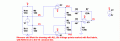
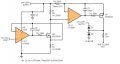
The three-amplifier instrumentation amplifier is a circuit well worth experimenting with understanding if you intend to do analog work. Either using simulation or "hand" calculations (I strongly recommend a spreadsheet for the latter) the effects of mismatch of the resistors will become apparent. It is matching of the ratios of the resistors that is important to "common mode rejection" - you want exactly the same gain for the inverting and non-inverting inputs. An ideal instrumentation amplifier will give zero output if the voltages at both inputs are identical, no matter the magnitude or frequency, within the range the amp can handle. In practical circuits, it is not just the rejection of the DC zero-signal (signal here meaning force, temperature, etc, depending on what the bridge is to measure) but rejection of common-mode noise that may be coupled onto the connecting wires. An understanding of "common mode noise" versus "normal mode" noise is essential - it will teach you why long individual wires running from board to board are bad.
For some applications you require very precise matching of the resistor ratios. For many practical applications matching of 0.1% to 1% may be acceptable. There is no point paying large amounts of money for 0.01% resistors if the system performance doesn't require it (concept here is "error budget"). One of the big advantages of using an IC instrumentation amp instead of building your own is that the critical resistor ratios are precisely matched by laser trimming and they track each other will with temperature variation and aging. Depending on the actual configuration of the circuit (there are about 3 common ways to arrange the amplifiers), it may not matter if the absolute values of the resistors are a long way from nominal ±20% could be fine, as long as matching in the pairs is very precise (which is a good thing, because making high-precision resistors on an IC is nearly impossible). As others have mentioned, there are some very nice, reasonably priced instrumentation amplifiers from several manufacturers.
You should be able to find a great deal of good information about differential amplifiers and instrumentation amplifiers on the web, in data sheets, applications notes and handbooks from TI, Analog Devices and Linear Technology.
The output of a bridge is directly proportional to the excitation voltage. If the bridge is perfectly balanced there will be no differential signal out, regardless of the excitation voltage. As soon as the bridge becomes unbalanced, then the effect of proportionality can be seen readily. If the excitation is not stable and free of noise the output of the bridge cannot be stable and free of noise.
If the output of the amplifier on the bridge is going to the input of an analog to digital converter that gets its voltage reference from exactly the same place as the bridge excitation, the variation in bridge output due to variation in the excitation voltage is cancelled. But in practice this will rarely happen.
The impression I get is that Arduino and other hobby boards typically just use the 5 V supply, perhaps with some filtering, as the reference for the ADC (some microcontrollers with ADCs have the option of an external ref, some have a reasonably good internal ref, some give no choice but to use the digital V+ as a ref). That's OK if the circuit is done very carefully and the demands are not high. If the 5 V used comes form a computer's USB port, it will be horrible. It will vary by hundreds of millivolts and have all sorts of noise on it. It is generally much better to use a decent voltage reference. I would use a 4.1 V reference (actually 4.096 V for a high-precision ref, since that makes scaling precise - 0.25, 0.50, 1.00, 2.00, etc. millivolts per count, depending on ADC resolution). The same reference could be buffered and used as excitation for the bridge, or you could use a different, stable low-noise reference for the bridge.
The three-amplifier instrumentation amplifier is a circuit well worth experimenting with understanding if you intend to do analog work. Either using simulation or "hand" calculations (I strongly recommend a spreadsheet for the latter) the effects of mismatch of the resistors will become apparent. It is matching of the ratios of the resistors that is important to "common mode rejection" - you want exactly the same gain for the inverting and non-inverting inputs. An ideal instrumentation amplifier will give zero output if the voltages at both inputs are identical, no matter the magnitude or frequency, within the range the amp can handle. In practical circuits, it is not just the rejection of the DC zero-signal (signal here meaning force, temperature, etc, depending on what the bridge is to measure) but rejection of common-mode noise that may be coupled onto the connecting wires. An understanding of "common mode noise" versus "normal mode" noise is essential - it will teach you why long individual wires running from board to board are bad.
For some applications you require very precise matching of the resistor ratios. For many practical applications matching of 0.1% to 1% may be acceptable. There is no point paying large amounts of money for 0.01% resistors if the system performance doesn't require it (concept here is "error budget"). One of the big advantages of using an IC instrumentation amp instead of building your own is that the critical resistor ratios are precisely matched by laser trimming and they track each other will with temperature variation and aging. Depending on the actual configuration of the circuit (there are about 3 common ways to arrange the amplifiers), it may not matter if the absolute values of the resistors are a long way from nominal ±20% could be fine, as long as matching in the pairs is very precise (which is a good thing, because making high-precision resistors on an IC is nearly impossible). As others have mentioned, there are some very nice, reasonably priced instrumentation amplifiers from several manufacturers.
You should be able to find a great deal of good information about differential amplifiers and instrumentation amplifiers on the web, in data sheets, applications notes and handbooks from TI, Analog Devices and Linear Technology.