How to Achieve 0.1 Hz Resolution from 0 to 10 kHz Using STM32 Timer?

Futurist

Joined Apr 8, 2025
939
Thanks for your reply.

I need to generate a frequency from 0 to 10,000.0 Hz with a resolution and step size of 0.1 Hz. I'm using a microcontroller, but PWM generation isn't accurate enough due to timer limitations (integer values only).

Is there any hardware solution available to achieve this level of precision, or are there any alternative ideas or approaches you would recommend?
This is why I mentioned accuracy, your OP speaks only of resolution not accuracy, you've stated desired resolution but you've not stated accuracy or stability, you need to state those numbers too.
 

MrChips

Joined Oct 2, 2009
35,032
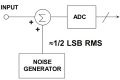
This is an interesting problem that requires dithering over a 10-second time interval.
I just realize that the algorithm is exactly the same as that used for dithering in raster graphics.
I will devise the algorithm.
 

BobTPH

Joined Jun 5, 2013
11,618
This is an interesting problem that requires dithering over a 10-second time interval.
I just realize that the algorithm is exactly the same as that used for dithering in raster graphics.
I will devise the algorithm.
Yep, same as Bresenham’s algorithm for drawing lines.
 

MrChips

Joined Oct 2, 2009
35,032
Dithering is used extensively in computer graphics and digital audio.
Here is an interesting history:

  1. …[O]ne of the earliest [applications] of dither came in World War II. Airplane bombers used mechanical computers to perform navigation and bomb trajectory calculations. Curiously, these computers (boxes filled with hundreds of gears and cogs) performed more accurately when flying on board the aircraft, and less well on ground. Engineers realized that the vibration from the aircraft reduced the error from sticky moving parts. Instead of moving in short jerks, they moved more continuously. Small vibrating motors were built into the computers, and their vibration was called dither from the Middle English verb "didderen," meaning "to tremble." Today, when you tap a mechanical meter to increase its accuracy, you are applying dither, and modern dictionaries define dither as a highly nervous, confused, or agitated state. In minute quantities, dither successfully makes a digitization system a little more analog in the good sense of the word. Ken Pohlmann, Principles of Digital Audio[3]

Reference: Dither - Wikipedia
 

MrChips

Joined Oct 2, 2009
35,032
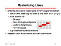
Also look up DDA (digital differential analyzer) and Bresenham's line algorithm.
These were mentioned earlier by @BobTPH in post #2 and post #25. This requires a division to calculate the slope of a line,
slope m = ∇y / ∇x

There is an algorithm that only uses additions and subtractions, as brought up by @nsaspook in post #3 and @WBahn in post #16.

The problem amounts to determining which pixels to enable when drawing a line from point (x1, y1) to (x2, y2) ?
Because of quantization in the discrete world, you end up with jagged lines.

1746882500511.png

Another requirement to add is that the same pixels must be invoked when drawing in the reverse direction, from (x2, y2) to (x1, y1). I had to do this because I also implemented selective erase where you could erase the same line traversing from either direction.

This jagged line problem is unavoidable with bi-level displays. With variable intensity pixels, adjacent pixels can be turned on with proportional brightness. This is known as anti-aliasing.

1746882823013.png
 

MrChips

Joined Oct 2, 2009
35,032
I have been giving this some serious thinking.

10,000 Hz with ±1 Hz step requires 14-bit resolution
50,000 Hz with ±1 Hz step requires 16-bit resolution
Thus
10,000.0 Hz with ±0.1 Hz step requires 17-bit resolution

You can do this with a VCO (voltage controlled oscillator) if you had 17-bit resolution.

This problem makes for an interesting exercise.
Since I already have a STM32F407 board, I can actually test out two possible solutions.
I plan to over-clock the STM32F407 to 200 MHz to increase the resolution and simplify the math.

1) Use the on-chip DAC and generate arbitrary waveforms, sine, triangle, square.
2) Use the DDA technique and modulate the values given to a timer module.

I can even do a spectral analysis of the resulting waveforms.
Time to get coding.
 

Futurist

Joined Apr 8, 2025
939
Dithering is used extensively in computer graphics and digital audio.
Here is an interesting history:

  1. …[O]ne of the earliest [applications] of dither came in World War II. Airplane bombers used mechanical computers to perform navigation and bomb trajectory calculations. Curiously, these computers (boxes filled with hundreds of gears and cogs) performed more accurately when flying on board the aircraft, and less well on ground. Engineers realized that the vibration from the aircraft reduced the error from sticky moving parts. Instead of moving in short jerks, they moved more continuously. Small vibrating motors were built into the computers, and their vibration was called dither from the Middle English verb "didderen," meaning "to tremble." Today, when you tap a mechanical meter to increase its accuracy, you are applying dither, and modern dictionaries define dither as a highly nervous, confused, or agitated state. In minute quantities, dither successfully makes a digitization system a little more analog in the good sense of the word. Ken Pohlmann, Principles of Digital Audio[3]

Reference: Dither - Wikipedia
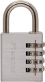
That's very interesting. I had an "air position indicator" from WW2 once, picked up at a surplus store. It was mechanical analogue, with a gyroscope and indicated LAT/LONG on two mechanical digit indicators, like we see on these padlocks.

1746885081598.png

It was beautiful, rotating circular slabs contacted by a bearing housed on the outside of a cylinder which could move across the disks surface, incredible but long ago lost.
 

nsaspook

Joined Aug 27, 2009
16,441
Also look up DDA (digital differential analyzer) and Bresenham's line algorithm.
These were mentioned earlier by @BobTPH in post #2 and post #25. This requires a division to calculate the slope of a line,
slope m = ∇y / ∇x

There is an algorithm that only uses additions and subtractions, as brought up by @nsaspook in post #3 and @WBahn in post #26.

The problem amounts to determining which pixels to enable when drawing a line from point (x1, y1) to (x2, y2) ?
Because of quantization in the discrete world, you end up with jagged lines.

View attachment 348860

Another requirement to add is that the same pixels must be invoked when drawing in the reverse direction, from (x2, y2) to (x1, y1). I had to do this because I also implemented selective erase where you could erase the same line traversing from either direction.

This jagged line problem is unavoidable with bi-level displays. With variable intensity pixels, adjacent pixels can be turned on with proportional brightness. This is known as anti-aliasing.

View attachment 348861
From my study book from years ago.
1746894009172.png
1746894027992.png

Elementary graphics stuff. I used a 8080/Z80 asm version in my old video processor.
https://forum.allaboutcircuits.com/threads/mixing-74-ls-hct-with-diode-logic.163109/post-1432058
 
Last edited:

WBahn

Joined Mar 31, 2012
33,076
Wow a similar history to the use of “bug” for errors in programming. Assuming that story is not apocryphal.
If you are referring to the infamous moth in the relay story, it is completely apocryphal. A "bug" in a system goes back nearly a century and probably quite a bit further. It was already an accepted definition of the word in many dictionaries.

That this was the case is pretty clearly evident from the wording in the journal in which the notation is, "First actual case of bug being found." That phrasing has no meaning unless the reader is assumed to already be familiar with the notion of finding bugs and grasps the humorous intent behind the moth being the first actual case of a bug being found.
 

MrChips

Joined Oct 2, 2009
35,032
Here are some good news.

I over-clocked the STM32F407 to 200 MHz (normally it is 168 MHz).
I have TIM2 (32-bit timer module) clocked at 100 MHz ( 10 ns resolution). I expected it to be 50 MHz. I don't know why this is happening. I will have to consult the Reference Manual for this.

I have TIM2 output toggling on every half-cycle. Thus there is no software delay.
With 10 ns resolution, there is no need to dither for output frequencies lower than 1 kHz.

For frequencies greater than 1 kHz, dithering is required. You need to modulate the timer count between N and N+1 count. There is a formula for determining the ratio of N:N+1.

I am working on the formula to determine this ratio.
 

Futurist

Joined Apr 8, 2025
939
Here are some good news.

I over-clocked the STM32F407 to 200 MHz (normally it is 168 MHz).
I have TIM2 (32-bit timer module) clocked at 100 MHz ( 10 ns resolution). I expected it to be 50 MHz. I don't know why this is happening. I will have to consult the Reference Manual for this.

I have TIM2 output toggling on every half-cycle. Thus there is no software delay.
With 10 ns resolution, there is no need to dither for output frequencies lower than 1 kHz.

For frequencies greater than 1 kHz, dithering is required. You need to modulate the timer count between N and N+1 count. There is a formula for determining the ratio of N:N+1.

I am working on the formula to determine this ratio.
Very interesting, one day I need to pick your brains about the STM32 clock stuff, each time I've tried to sit down and get a handle on it I've been left confused as hell.
 

MrChips

Joined Oct 2, 2009
35,032
DDA - Digital Differential Analyzer

I will describe what is a DDA.
Then I will apply this technique to the problem of generating a waveform using a hardware timer module.
Finally, I will demonstrate DDA using a real example on the STM32F407 MCU.

What is the DDA algorithm?
Many computations involve division of integer values giving rise to non-integer (fractional) results. Floating-point arithmetic takes processing time in the absence of a hardware FPU (floating-point unit). With only integer arithmetic allowed, one has to keep track of the fractional parts as integer values.

An example of the application of DDA is in the drawing of a straight line in computer graphics. In the general case, one is required to draw a straight line from (x1, y1) to (x2, y2) by enabling individual pixels along the path.

The general equation of a straight line can be written as,

y = mx + c

where m represents the slope of the line,

m = (y2 - y1)/(x2 - x1) = ∇y/∇x

To simplify this example, we will restrict analysis to the case where m is in the range from 0 to 0.5, in other words ∇y ≤ ∇x.
Since ∇x ≥∇y, there is a pixel at every increment of x. Thus, for every increment of x, we add the value ∇y to a register R.
When R ≥ ∇x, we subtract ∇x from R and increment y.

(Note that the initial value of R is set to ∇y/2.)

Waveform Generator
Assume that the clock frequency of the timer module is M Hz
Clock period = 1/M seconds
Target output frequency = f Hz
Output period = 1/f seconds

Since the timer module will be toggling the output at every half-cycle, we need the half-cycle period.
Half-cycle period = 1/2f seconds
Timer count = half-cycle period / clock period = M/2f

Since the target frequency f will be given with 0.1Hz resolution, we scale both numerator and denominator by 10 before performing the division.
Timer count N = 10M/20f

We perform this division using 64-bit unsigned integer values by declaring M, f, N as uint64_t data type.

If we use the value N, the target frequency could be too high.
If we use the value N+1, the target frequency will be to low.
In other words, the correct value to use is between N and N+1. Hence we dither (modulate) between N and N+1.

This is where we apply the DDA algorithm. Rather than ignoring the fractional part of the division, we need to take it into account. We will use an 8-bit fraction by multiplying the numerator by 256.

N x 256 = 2560M /20f = R

We save the least 8 bits of R as the fraction, which we will call FRAC.
We right-shift R by 8 bits to give N.

Now on with the DDA show.
We set the timer count to N. At every iteration, we add FRAC to a register FR. When the register exceeds 255, we subtract 256 from FR and set the timer count to N+1 for this one time.

A Real Example
We over-clock the STM32F407 to 200 MHz.
Assume counter clock frequency = M Hz = 100 000 000 Hz = 1 x 10^8 Hz
Clock period = 1 / M seconds = 1 x 10^-8 seconds

Our target output frequency f = 9 876.8 Hz (chosen at random)
Target period = 1/f = 101.247 μs
Half cycle period = 50.62368 μs
(Note here that the integer part will become 5062 and the fractional part is 0.368 when we divide by 0.01 μs clock period.)

Assuming fractional part is 8 bits
Timer count = (10M x 256)/(20f) = (256 000 000 000) / (2 x 98768) = 1 295 966 (truncated)

Integer part is 5062. Fractional part is 94/256 or about 36%
If we use 5062, the resulting cycle period is 2 x 5062 x 0.01 us = 101.24 μs
The frequency is 9 877.5 Hz which is too high.

If we use 5063, the resulting cycle period is 2 x 5063 x 0.01 us = 101.26 μs
The frequency is 9 875.5 Hz which is too low

Our target frequency of 9 876.8 Hz lies somewhere in between the two values.
The ideal solution is 64% @ 5062 and 36% @ 5063.

64 x 2 x 5062 x 0.01 / 100 = 647936 x 10^-4 μs
36 x 2 x 5063 x 0.01 / 100 = 364536 x 10^-4 μs
Sum = 1012472 x 10^-4 μs
Frequency = 9 876.8 Hz (with truncation)

Applying the DDA algorithm, at each iteration, we add 94 into the fractional register (FR). When FR exceeds 255, we subtract 256 from FR. We also set the timer counter to (N+1), in other words, 5063 for this step only. This procedure is performed in the timer update ISR (interrupt service routine).

For this application, the DDA technique is not necessary for frequencies lower than 2250 Hz. The 10 ns resolution is fine enough to handle these cases.

Credit goes to @WBahn for first suggesting the integer-fraction solution in post #16.
 

MrChips

Joined Oct 2, 2009
35,032
Incidentally, a few years back I was experimenting with a direct conversion digital radio using STM32F407.
I was not using DDA to generate my sine waves. I will have to go back and apply this technique.
 
Top