
How do I modify my PIC microcontroller program to deliver 150 hz also with the existing 1hz output

BobTPH

Joined Jun 5, 2013
11,616
To summarize the gist of the excellent post above:

To get two accurate frequencies generated, you need a crystal that is a multiple of BOTH frequencies.

Since 150Hz is already a multiple of 1Hz, any multiple of 150Hz will work. That does not include 16MHz, 4MHz, or 32768Hz.

For those who questioned how you would use a 32768Hz crystal: PICs have a secondary oscillator input that allows you clock the timers with a different frequency than the processor clock frequency.
 

Thread Starter

Arjune

Joined Jan 6, 2018
354
@Arjune
what is your aim here ?
you have all but said your not learning,
you are picking answeres from humans or AI

you evidently are not in a position to sell and support this ,
and it would be flagged up as plagerisum if it was presented as your work at a college,

we might be able to help you more if we knew your aims of this work,
Using AI is not plagerism, it is not intellectual property-it is the property of intelligence. Anyway, I'm sorry if I touched some nerves. My aim is just to explore possibilities of something I have not done before.
 

drjohsmith

Joined Dec 13, 2021
1,630
Using AI is not plagerism, it is not intellectual property-it is the property of intelligence. Anyway, I'm sorry if I touched some nerves. My aim is just to explore possibilities of something I have not done before.
My apologies @Arjune
teachers head on there,
using AI is considered plagerisum in academic circles, as its not your own work,,

your posts and way of working had me worried for you,
I now understand better where your comming from and aims,

I wish you the best in your endevours ,
 

drjohsmith

Joined Dec 13, 2021
1,630
To summarize the gist of the excellent post above:

To get two accurate frequencies generated, you need a crystal that is a multiple of BOTH frequencies.

Since 150Hz is already a multiple of 1Hz, any multiple of 150Hz will work. That does not include 16MHz, 4MHz, or 32768Hz.

For those who questioned how you would use a 32768Hz crystal: PICs have a secondary oscillator input that allows you clock the timers with a different frequency than the processor clock frequency.
thanks @BobTPH
the 32.768 Khz was raised by another member, cant remember whom.
my aim re the 32.768 Khz comment was to highlight for the OP ,
that they coukd not just switch the 16Mhz resonator they currently have for a 32.768 Khz one without spreading the discsion further unless the OP wanted to.
 

Thread Starter

Arjune

Joined Jan 6, 2018
354
Threre are may different ways to divide down from 4 Mhz to 1 Hz as you always finish up with dividing by 4000000.
But you can't divide 4Mhz by an integer to get 150 hz. (4000000/150 = 26666.666666666666666666666666667)
If you buy a 15 Mkz crystal you can divide by an integer to get to 150 Hz. With a 15 Mhzcrystal the clock frequency will be
15000000/4 = 3750000 hz.
3750000/150 = 25000
You start by generating an exact 150 hz using timer 1 (This is what the present code does .)
In software you then count 150 cycles of 150 hz to get down to an exact 1 hz.
It would help us to help you if you explained why you need 1hz and 150 hz for your clock. (The only thing I can think of is that the 150 hz is for mltiplexing the display.)
How accurate does the clock have to be and what is it being used for ? If it needs to be very accurate then using the cheap crystals that are used for the CPU clock frequency will not be accurate enough.
Posting the schematic of the clock that you need the two fequencies for would be a help.
Threre are methods of generating accurate frequencies using a GPS receiver.
There are also standard frequency transmissions in most countries that can be used to generate accurate frequencies.
Another accurate frequency source for 1Hz and 32768 hz is the DS3231 RTC chip. I bought one of these wrote some code to set it and read it's output. I then put it to one side for a couple of years befor using it in a project and it was only a few seconds out after all that time..
Les.
The schematic for modulus 60 counter for the clock is attached. J5 is clock in for the 1hz clock and 150 hertz for setting the clock. J6 goes to the next modulus 60 counter for minutes. SW1 is to count up or down. J3 is power of 5 volts. J4 is not needed. J1 & J2 goes to a 7 segment decoder for the display like a cd4511. Q1 serves as an inverter. Q2 serves as a driver for the next stage (modulus 60 or modulus 12).
 

Attachments

drjohsmith

Joined Dec 13, 2021
1,630
The schematic for modulus 60 counter for the clock is attached. J5 is clock in for the 1hz clock and 150 hertz for setting the clock. J6 goes to the next modulus 60 counter for minutes. SW1 is to count up or down. J3 is power of 5 volts. J4 is not needed. J1 & J2 goes to a 7 segment decoder for the display like a cd4511. Q1 serves as an inverter. Q2 serves as a driver for the next stage (modulus 60 or modulus 12).
is that your circuit ?
sw1 seems to short vdd to vss !
q1, what makes the base low ?

you might want to start a new post in the hardware forums just about this circuit else the pic conversation might get confused between the hardware of this counter and the pic code.
 

Thread Starter

Arjune

Joined Jan 6, 2018
354
is that your circuit ?
sw1 seems to short vdd to vss !
q1, what makes the base low ?

you might want to start a new post in the hardware forums just about this circuit else the pic conversation might get confused between the hardware of this counter and the pic code.
The circuit is a modification of a circuit I designed a few years ago that I applied to 5 clocks I built. In the circuit before I used 1 gate of a 4071 quad OR gate. I don't see a short with sw1. Where do you seem to see the short? Q1 is low because of R1 through R2.
 
Hi there. saw this. looks like a fun project. it's actually pretty easy if you understand the chip. the '627 has numerous different ways to do this. the one I'm posting here is what I think is the easiest to understand.

the requirement is to generate accurate 150Hz, then divide-by-150 for the 1Hz. this design has ±128 cycles (±64μs) of jitter, and a maximum theoretical error of 1 second/year.

I just modified the AI-generated Timer1 thing that was posted. Timer1 is actually two cascaded timers. One (TMR1L) has a fixed period of 256, the other (TMR1H) is settable. thus, divide your incoming frequency by 256 in TMR1L, then use TMR1H to get to 300 events per second (toggle the 150Hz pin twice per cycle), then divide by 150 and toggle the 1Hz pin.

some free advice:
  • DO NOT use the prescaler. it resets when writing to TMR1, which throws away between 0 and 7 cycles. this directly prevents you from generating a correct interval.
  • DO NOT write to TMR1L. it is a fixed /256 frequency divider. embrace it.

OK. here we go:
  • Your incoming frequency is Fosc which you can specify as 16MHz. after you perform accurate measurements of your oscillator, simply modify Fosc to be that value, and recompile the code.
  • the chip uses a 4-phase clock, so use (Fosc/4) in the equations.
  • as said before, TMR1L is a divide-by-256 frequency divider, so use /256 in the equations.
  • the 150Hz Fout output requires 2 events to toggle each of the edges, so use (2*Fout) in the equations.
  • do the math, and you get a required TMR1H divisor of (16MHz/4)/256/(2*150)=52.083333.
    • that fractional part is 1/12. thus for every 12 events, you could 11 at 52, and then 1 at 53. you could use a counter, but it will not work as well if your actual oscillator frequency is different.
    • instead, use a fractional modulator that generates 52 and 53 in the correct proportion. multiply the divisor by 2^24, and it is 32 bits with the TMR1H value in the upper 8 bits and then 24 bits of fraction. on every 300Hz interrupt, add to the accumulator, and copy the upper byte TMR1H. the low 24 bits will generate a carry at the correct rate.
  • TMR1H counts upward, so subtract in the accumulator every time, and load a negative number into TMR1H.


(you can write to TMR0 and TMR1L if you VERY MUCH know what you're doing. it will get you to near-zero jitter. that topic is not for this thread.)

Please see the code below .....................

_____________________________________________________________________________________________


C-like:
// Configuration Bits: 16MHz HS Crystal, Watchdog Off, MCLR On, LVP Off
#include <xc.h>
#pragma config FOSC = HS, WDTE = OFF, PWRTE = ON, MCLRE = ON, BOREN = OFF, LVP = OFF, CPD = OFF, CP = OFF


#define _XTAL_FREQ 16000000 // 16 MHz Crystal

#define OUT_1      PORTBbits.RB0

#define OUT_150    PORTBbits.RB3


#define Fout 150 //required output frequency


#define Fosc 16000000.000000 // measured value of oscillator frequency


#define TMR1L_frequency ((Fosc/4) /256)

#define TMR1H_divisor (TMR1L_frequency / (2*Fout))

#define TMR1H_period ((uint32_t)((TMR1H_divisor *((double)(1L<<24))) +0.5))


union {

    uint32_t full_precision;

    uint8_t B[4];

} accumulator;


uint8_t timer_counter = 0;


void __interrupt() isr(void) {

    if (PIR1bits.TMR1IF) { // Check Timer 1 Overflow Flag


        accumulator.B[3] = 0;

        accumulator.full_precision -= TMR1H_period;

        TMR1H = accumulator.B[3];


        OUT_150 = ~OUT_150; // Toggle the pin


        timer_counter++;

        if (timer_counter >= 150) {

            OUT_1 = ~OUT_1; // Toggle the pin

            timer_counter = 0;

        }

        PIR1bits.TMR1IF = 0; // Clear interrupt flag

    }

}


void main(void) {

    CMCON = 0x07;      // Disable comparators to use PORTA/B as digital I/O

    TRISBbits.TRISB0 = 0; // Set RB0 as output

    TRISBbits.TRISB3 = 0; // Set RB3 as output

//     CLOCK_OUT = 0;


    // Timer 1 Configuration

//do not use the prescaler when writing to TMR1    T1CONbits.T1CKPS = 0b11; // 1:8 Prescaler

    T1CONbits.TMR1CS = 0;    // Internal clock (Fosc/4)

//     TMR1H = 0x3C;            // Initial preload

//     TMR1L = 0xB0;


    // Interrupt Configuration

    PIE1bits.TMR1IE = 1;     // Enable Timer 1 interrupt

    INTCONbits.PEIE = 1;     // Enable peripheral interrupts

    INTCONbits.GIE = 1;      // Enable global interrupts

    T1CONbits.TMR1ON = 1;    // Start Timer 1


    while (1) {

        // Main loop remains empty; logic is handled in ISR

    }

}
 
Last edited by a moderator:
I'm new here. let's post that code again.

Code:
#include <xc.h>

// Configuration Bits: 16MHz HS Crystal, Watchdog Off, MCLR On, LVP Off
#pragma config FOSC = HS, WDTE = OFF, PWRTE = ON, MCLRE = ON, BOREN = OFF, LVP = OFF, CPD = OFF, CP = OFF

#define _XTAL_FREQ 16000000 // 16 MHz Crystal
#define OUT_1      PORTBbits.RB0
#define OUT_150    PORTBbits.RB3


#define Fout 150 //required output frequency

#define Fosc 16000000.000000 // measured value of oscillator frequency

#define TMR1L_frequency ((Fosc/4) /256)
#define TMR1H_divisor (TMR1L_frequency / (2*Fout))
#define TMR1H_period ((uint32_t)((TMR1H_divisor *((double)(1L<<24))) +0.5))

union {
    uint32_t full_precision;
    uint8_t B[4];
} accumulator;


uint8_t timer_counter = 0;

void __interrupt() isr(void) {
    if (PIR1bits.TMR1IF) { // Check Timer 1 Overflow Flag

        accumulator.B[3] = 0;
        accumulator.full_precision -= TMR1H_period;
        TMR1H = accumulator.B[3];

        OUT_150 = ~OUT_150; // Toggle the pin

        timer_counter++;
        if (timer_counter >= 150) {
            OUT_1 = ~OUT_1; // Toggle the pin
            timer_counter = 0;
        }
        PIR1bits.TMR1IF = 0; // Clear interrupt flag
    }
}

void main(void) {
    CMCON = 0x07;      // Disable comparators to use PORTA/B as digital I/O
    TRISBbits.TRISB0 = 0; // Set RB0 as output
    TRISBbits.TRISB3 = 0; // Set RB3 as output
//     CLOCK_OUT = 0;

    // Timer 1 Configuration
//do not use the prescaler when writing to TMR1    T1CONbits.T1CKPS = 0b11; // 1:8 Prescaler
    T1CONbits.TMR1CS = 0;    // Internal clock (Fosc/4)
//     TMR1H = 0x3C;            // Initial preload
//     TMR1L = 0xB0;

    // Interrupt Configuration
    PIE1bits.TMR1IE = 1;     // Enable Timer 1 interrupt
    INTCONbits.PEIE = 1;     // Enable peripheral interrupts
    INTCONbits.GIE = 1;      // Enable global interrupts
    T1CONbits.TMR1ON = 1;    // Start Timer 1

    while (1) {
        // Main loop remains empty; logic is handled in ISR
    }
}
 

LesJones

Joined Jan 8, 2017
4,522
drjohsmith
I do not agree that SW1 can short Vcc to Vdd. Pin 4 will never be connected to pin 6. In one position it connects pin 5 to pin 4 (Vdd) and in the other position it connects pin 5 to pin 6 (Vcc) This changed the state of the up/down pin on both conters.

Arjune
From your post #65 I understand that this is just being used as a domestic clock. So you do not require very high accuracy of the 1 hz clock. (But better than the accuracy of the 16 Mhz CPU crystal.) I also understand that the 150 hz clock is very non crytical.
If 151.7 hz wa close enough to setting the clock then you could us 32768 hz crystal and in the idle loop of the code you would just make loop of 27 instruction cycles and each time round the loop toggle an I/O pin. this is very easy to do in assembler but I have no idea how to do it in C. Others could probably tell you how to do it in C.
Les.
 
Last edited:

Thread Starter

Arjune

Joined Jan 6, 2018
354
I'm new here. let's post that code again.

Code:
#include <xc.h>

// Configuration Bits: 16MHz HS Crystal, Watchdog Off, MCLR On, LVP Off
#pragma config FOSC = HS, WDTE = OFF, PWRTE = ON, MCLRE = ON, BOREN = OFF, LVP = OFF, CPD = OFF, CP = OFF

#define _XTAL_FREQ 16000000 // 16 MHz Crystal
#define OUT_1      PORTBbits.RB0
#define OUT_150    PORTBbits.RB3


#define Fout 150 //required output frequency

#define Fosc 16000000.000000 // measured value of oscillator frequency

#define TMR1L_frequency ((Fosc/4) /256)
#define TMR1H_divisor (TMR1L_frequency / (2*Fout))
#define TMR1H_period ((uint32_t)((TMR1H_divisor *((double)(1L<<24))) +0.5))

union {
    uint32_t full_precision;
    uint8_t B[4];
} accumulator;


uint8_t timer_counter = 0;

void __interrupt() isr(void) {
    if (PIR1bits.TMR1IF) { // Check Timer 1 Overflow Flag

        accumulator.B[3] = 0;
        accumulator.full_precision -= TMR1H_period;
        TMR1H = accumulator.B[3];

        OUT_150 = ~OUT_150; // Toggle the pin

        timer_counter++;
        if (timer_counter >= 150) {
            OUT_1 = ~OUT_1; // Toggle the pin
            timer_counter = 0;
        }
        PIR1bits.TMR1IF = 0; // Clear interrupt flag
    }
}

void main(void) {
    CMCON = 0x07;      // Disable comparators to use PORTA/B as digital I/O
    TRISBbits.TRISB0 = 0; // Set RB0 as output
    TRISBbits.TRISB3 = 0; // Set RB3 as output
//     CLOCK_OUT = 0;

    // Timer 1 Configuration
//do not use the prescaler when writing to TMR1    T1CONbits.T1CKPS = 0b11; // 1:8 Prescaler
    T1CONbits.TMR1CS = 0;    // Internal clock (Fosc/4)
//     TMR1H = 0x3C;            // Initial preload
//     TMR1L = 0xB0;

    // Interrupt Configuration
    PIE1bits.TMR1IE = 1;     // Enable Timer 1 interrupt
    INTCONbits.PEIE = 1;     // Enable peripheral interrupts
    INTCONbits.GIE = 1;      // Enable global interrupts
    T1CONbits.TMR1ON = 1;    // Start Timer 1

    while (1) {
        // Main loop remains empty; logic is handled in ISR
    }
}
I used this code to program the microcontroller. It was about three seconds slow with the 16mhz crystal in a span of 10 hours using the 1hz output. I;m in my home in Rockland and not the Bronx where I have my oscilloscope so I couldn;t measure the crystal frequency with the oscilloscope if it is at all possible. I have a laptop in Rockland to program the microcontroller.
 
I used this code to program the microcontroller. It was about three seconds slow with the 16mhz crystal in a span of 10 hours using the 1hz output. I;m in my home in Rockland and not the Bronx where I have my oscilloscope so I couldn;t measure the crystal frequency with the oscilloscope if it is at all possible. I have a laptop in Rockland to program the microcontroller.
Great to hear from you!

You did great job measuring the frequency. Looks like your accuracy is -3 seconds per (10 hours * 3600 seconds/hour) or -1 part in 12000, or -83ppm. The error in your crystal frequency is 16000000*(-1/12000) or -1333Hz. Subtract to get (16000000-1333) or an actual crystal frequency of 15998667Hz. Change Fosc to that value, and rebuild. For your copy/paste convenience,
updated crystal frequency:
#define Fosc 15998667.000000 // measured value of oscillator frequency
 

drjohsmith

Joined Dec 13, 2021
1,630
I used this code to program the microcontroller. It was about three seconds slow with the 16mhz crystal in a span of 10 hours using the 1hz output. I;m in my home in Rockland and not the Bronx where I have my oscilloscope so I couldn't measure the crystal frequency with the oscilloscope if it is at all possible. I have a laptop in Rockland to program the microcontroller.
Just a note
you say "measure the crystal frequency with the oscilloscope"
On the screen , one cycle of 16 MHz, and one cycle of 15998667Hz ,is going to look the same
The jitter on sampling is going to be more than the difference, and your using the scopes trace accuracy against the clock your measuring,
Unlikely your going to notice any difference,

100 ppm tolerance oscillator is of the base quality, you can purchase better quality , lower ppm parts,
check if its a resonator or a crystal
 

LesJones

Joined Jan 8, 2017
4,522
Here is a program to genereate 1hz and close to 150 hz at the same time. (It is not exactlry 150 hz itis 148.9 hz)
frequencygenerator:
;pPic clock frequency generator


;PIC16f628A, set for 32768 Hz XTAL, WDT OFF, POR on
;Instruction time at 8192 HZ is 122.0703125 us
;For 1.0 hz
; 500000us / 122.0703125us  = 4096 (Half cycleo f 1 hz)
; Timer1 overflows at a count of 65536  (2^16)
; So need to preload Timer1 with 65536 - 4096 = 61440  (0xF000)
; As there is a number of instructions between the interrupt and the timmer starting again
; we need to correct for this (There are 13 (0x0D) instruction cycles)
; so we need to reduce the count by 13, So making the preload 0xF00D should do this.
; This correction was not enough. Had to increase to 18 (0x12) to get  1 HZ
; My frequency counter only has a resolution of 10 uS when measuring the period of a waveform.
; I think these 5 instruction times must be the time between the interupt and the start of the code
; in the interrupt service routine


; For 151.7 hz from the main loop it needs to be 27 instructon cycles long.
; Can get slightly better if we have high for 27 cycles and low for 28 cycles
; this gives 148.9 hz

;*******************************************************************************
; Pin Assignments
;*******************************************************************************
;
;    PIC signals
;
    #DEFINE        hz1_out        PORTB, 0    ;(Pin 6 )
    #DEFINE        hz150_out    PORTA, 0    ;(Pin 17 )
;

    list P=16f628
    #include "p16f628a.inc"
    __config _LP_OSC & _WDT_OFF & _PWRTE_ON & _LVP_OFF

;written in MASM

    STATUS_TEMP         EQU 0x7e        ; Exists in all banks
    W_TEMP              EQU 0x7f        ; Exists in all banks

Start:
        ORG 0x00    
    GOTO Init        ;initialise hardware.

    ORG    0x04        ;Interrupt vector
    GOTO ISR        ;interrupt serice troutine

Init    BCF INTCON,GIE          ;turn off global interrupts

    MOVLW     0x07            ; activate PORTA for PC16F628 as digital
    MOVWF    CMCON
       
;Init PORTA
    BSF     STATUS,5    ;Select register bank 1
    MOVLW    B'00000000'    ;All PORTA pins as outputs
    MOVWF    TRISA

;INIT PORTB
    MOVLW    B'00000000'    ;All PORTB pins as outputs
    MOVWF    TRISB
    BCF     STATUS,5    ;Select register bank 0

    BSF    PORTA,0        ;Pin 16

; INIT TMR1
    MOVLW    B'00000100'    ;Clock source FOSC, 1:1 prescale, Dedicated Timer1 oscillator circuit disabled,
                                ;Do not synchronize external clock input, Timer off

    MOVWF    T1CON        ;With 32768 hz clock timer will increment every 122.0703125 us

;Preset TMR1
    MOVLW    0x12
    MOVWF    TMR1L
    movlw   0x0F0                   ; For 0.5 second interrupts.
    movwf   TMR1H  
;Enable TMR1 interrupts
    BSF    STATUS,5    ;Select register bank 1
    MOVLW    b'00000001'    ;Enable timer1 interrupt
    MOVWF    PIE1
    BCF    STATUS,5    ;Select register bank 0

;Start TMR1
       BSF     T1CON, TMR1ON    ;Start timer 1

bsf     INTCON, PEIE        ;PEIE: Peripheral Interrupt Enable bit
    BSF INTCON,GIE          ;turn on global interrupts

    GOTO Main_program_loop     ;


ISR:    ; assume that it takes 1 cycle to start interrupt code    1 cycle
    movwf   W_TEMP           ;Save registers "W" & "STATUS"     1 cycle
    swapf   STATUS, W        ;                 1 cycle
    clrf    STATUS        ;                 1 cycle
    movwf   STATUS_TEMP      ;                 1 cycle

    btfss   PIR1, TMR1IF          ;timer     ;         2 cycle
    goto    intDone            ;Not timer1 interrupt
   
    BCF     T1CON, TMR1ON    ;Stop timer 1            1 cycle
    MOVLW   0x012    ;                     1 cycle
    MOVWF   TMR1L        ;                 1 cycle
    movlw   0x0F0                   ; For 0.5 second interupts. 1 cycle
    movwf   TMR1H                   ; Restart the timer        1 cycle
    BSF     T1CON, TMR1ON    ;Start timer 1            1 cycle

;                            Total of 13 cycles to this point


    bcf     PIR1, TMR1IF            ; Must clear interrupt flag 1 cycle

; Toggle PORTB,0
    MOVLW    0x01    ;Set bit 0
    XORWF    PORTB

intDone:          ;Restore registers "W"  & STATUS
    swapf   STATUS_TEMP, W
    movwf   STATUS
    swapf   W_TEMP,F
    swapf   W_TEMP, W
    retfie            ;Return from interupt
;
; End of interrupt.


Main_program_loop:  ;Needs to be 27 instructions long  (27 - 4 = 23 So 23 NOP instructions required )


;Generate 1 cycle of 150 hz

    BSF    PORTA, 0    ;Set output high          

; Lazy way -
; Just use 26 NOP instructions.
    NOP
    NOP
    NOP
    NOP
    NOP
    NOP
   
    NOP
    NOP
    NOP
    NOP
    NOP
    NOP

    NOP
    NOP
    NOP
    NOP
    NOP
    NOP
   
    NOP
    NOP
    NOP
    NOP
    NOP
    NOP

    NOP
    NOP            27 cycles from start ofloop (High for 27 cycles )

    BCF    PORTA, 0  ;1 cycle    Set output low

    NOP            ;     now 25     NOPs  (Low for 28 cycles)
    NOP
    NOP
    NOP
    NOP
    NOP

    NOP
    NOP
    NOP
    NOP
    NOP
    NOP

    NOP
    NOP
    NOP
    NOP
    NOP
    NOP
   
    NOP
    NOP
    NOP
    NOP
    NOP
    NOP

    NOP

    GOTO Main_program_loop     ;    2 cycle

    END                ; End of rogram
I have attached the .HEX file to program a PIC16F628A using a PICkit 2 or 3 It sould aldso work on a PIC16F627.
The 1hz output is on PORTB bit 0 (Pin 6) and the 148.9 hz is on PORTA bit 0 ( Pin 17)
See figure 14-1 on page 97 of the data sheet for connecting the 32768 hz crystal. For resistor RS I usr a 100K resistor
You can trim the crystal onto frequency by ising a variable capacitorin place of one one of the fixd capacitors.
Les.
 

Attachments

drjohsmith

Joined Dec 13, 2021
1,630
I can't get my 32,768hz crystal to oscillate and so I didn't try the assembly program.
As mentioned earlier
You can't take a circuit designed for day a 16 MHz crystal , and expect it to work with the 32.768 Khz
It's like trying to use jet fuel or diesel , similar but different.
How did you change your circuit to accept the 32.768 Khz ,
 

LesJones

Joined Jan 8, 2017
4,522
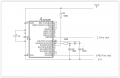
This is the circuit that I used.

Screen Shot 01-16-26 at 12.45 PM.PNG
I found that some of the 32Khz crystals that I tried did not oscilate without the 100K resistor.
Les.
 

drjohsmith

Joined Dec 13, 2021
1,630
This is the circuit that I used.

View attachment 362153
I found that some of the 32Khz crystals that I tried did not oscilate without the 100K resistor.
Les.
Not confident on that pic , but which of the oscillators have you connected the crystal to ?
How did you calculate the capacitor and resistor values ?
Low frequency crystals like 32.768 ,khz are notorious to make oscilate reliably , they are very dependent on PCB layout and circuit
You also need to ensure it is a LP mode
 
Top





