 Facebook
 Google
 GitHub
 Linkedin
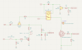
I have the attached design for determining if there is continuity through an igniter. The good news is the circuit only uses ~ 5 - 10 mA to test the igniter, so there is no danger of the igniter igniting. The bad news is it does not detect when/if the igniter breaks when it is being ignited - ~2-4A.
The order of operations:
1. Shut off 12V (switch etc. not shown).
2. Connect igniter to terminal (~4 foot wires)
3. Turn on 12V and set Energize Igniter to ~ 3V
4. See green LED is on and test continuity with buzzer switch. Controller reads Continuity OK as ~3V. If no continuity through the igniter ( i.e. bad connection, bad igniter, etc.) then the green LED is not on and the Controller reads Continuity OK ~ 0V. The Continuity buzzer does not sound when the Continuity Check button is pressed.
5. Walk away.
6. Switch Relay Enable to 3.3V and watch the igniter burn with ~2-4 A flowing through the igniter for ~ 1-5 sec
In step 6, the Q13 is off, so there are no continuity indicators (green LED or Continuity OK). I would like to modify the circuit so
1. the continuity LED stays on until/if the igniter actually breaks
2. Continuity OK stays at 3V until/if the igniter actually breaks - most important so the Controller can reset the igniter circuit before the 5 sec time out concludes.
3. The continuity buzzer is irrelevant at this point as the "smart" user is too far away to push the Continuity Check button.
Attachments
-
 56.4 KB Views: 19


