How do I modify my PIC microcontroller program to deliver 150 hz also with the existing 1hz output

drjohsmith

Joined Dec 13, 2021
1,630
In about 12 hours (I'm guessing) the pic circuit is about 1 second fast with 32pf (10pf in parallel with 22pf) loading capacitors on the 32khz crystal.
View attachment 362623
That crystal is a long way away from the ic.and capacitors ..that's where the random caps itsncd is likely to be ..
That will also introduce drift as it will vary as your hand is near it ..
I'd use an oscillator instead of the crystal / resonator ,
 

Thread Starter

Arjune

Joined Jan 6, 2018
354
That crystal is a long way away from the ic.and capacitors ..that's where the random caps itsncd is likely to be ..
That will also introduce drift as it will vary as your hand is near it ..
I'd use an oscillator instead of the crystal / resonator ,
Is there a cheap 8-pin dip microcontroller I could buy that is 8-bit that uses MP lab IDE with that is not static sensitive?
I attached leads to my trimmer capacitor and is using it with the circuit. It is on pin 13 to ground at oscillator in in parallel with a 20pf fixed capacitor. I am checking timing for possible adjustments to the trimmer capacitor. The trimmer capacitor is 20 pf also as measured with my multimeter. My pic 16f628a has device ID faults and I am running out of chips. Is there some cheap 8 pin dip 8-bit microcontrollers I could buy on eBay or Ali express that is not static sensitive. I still want to use it on my mp lab IDE/IPE. It also has to support a 32 kilohertz crystal and my pickit3 programmer.
 

drjohsmith

Joined Dec 13, 2021
1,630
Is there a cheap 8-pin dip microcontroller I could buy that is 8-bit that uses MP lab IDE with that is not static sensitive?
I attached leads to my trimmer capacitor and is using it with the circuit. It is on pin 13 to ground at oscillator in in parallel with a 20pf fixed capacitor. I am checking timing for possible adjustments to the trimmer capacitor. The trimmer capacitor is 20 pf also as measured with my multimeter. My pic 16f628a has device ID faults and I am running out of chips. Is there some cheap 8 pin dip 8-bit microcontrollers I could buy on eBay or Ali express that is not static sensitive. I still want to use it on my mp lab IDE/IPE. It also has to support a 32 kilohertz crystal and my pickit3 programmer.
As above.
All chips are static sensitive .
But are you certain it's static ?
If so , suggest you invest in an anti static mat and wrist strap..
Depending on your meter , that could also be damaging the chips , esspecialy if you doing things like capacitance or resistance measuring in circuit.
 

LesJones

Joined Jan 8, 2017
4,522
I had a plan to use a 32768 hz crystal on timer 1 oscillator and use the 4 Mhz internal oscillator for the system clock for the 150 hz output. The code worked with each of these outputs working individually but when but when both both options were configured together I got configuration errors when programming the PIC (Using a PICKIT3 and PICKIT3 software.) If I used an external 4 Mhz crystal for the system clock it all worked. I suspect that using 2 crystals would not suit your requirements.
If you used one of the oscillators that Ya’akov suggested (The 32768hz version) for timer 1 clock then you could get both outputs and it would also meet your accuracy requirements.
(Note. I have ordered one of these oscillators to replace the 100 Khz crystal in my frequency counter. This will improve it's accuracy.)
To clear the ID error try using the erase option in the PICKIT3 software to get the PIC back to the same stae as a new 1.
(The PICKIT 3 software is on the CD that is supplied with th PICKIT3. Or from the Microchip website)
Les.
 

LesJones

Joined Jan 8, 2017
4,522
I have modified the idea from post #125 to run on a PIC12F1840 (An 8 pi PIC.) It works OK om this chip.)
Here is the assembler code.


Code:
;            Program to generate 1 hz anf 150 hz outputs

;
;******************************************************************************************
;
;        OSC      : Internal OSC 4 MHz
;
;******************************************************************************************
        list P=12F1840,ST=OFF,R=DEC
        #INCLUDE  "P12F1840.inc"

       __CONFIG _CONFIG1,  _FOSC_INTOSC & _WDTE_OFF & _PWRTE_OFF &  _MCLRE_OFF & _CP_OFF & _CPD_OFF & _BOREN_OFF & _CLKOUTEN_OFF & _IESO_OFF & _FCMEN_OFF


       __CONFIG _CONFIG2, _WRT_OFF & _PLLEN_OFF & _STVREN_OFF & _BORV_HI & _LVP_OFF


;
;*******************************************************************************
; Pin Assignments
;*******************************************************************************
;
;    PIC signals


; I/O pin use
;    RA0       1 hz out             (Pin 7)         (To pin 4 on programmer connection)
;    RA1       150 hz out         (Pin 6)         (To pin 5 on programmer connection)
;    RA2                     (Pin 5)
;    RA3                  (Pin 4)    NOTE THIS PIN CAN ONLY BE USED AS AN INPUT.
;  
;    RA4     T1OSO             (Pin 3)
;    RA5    T1OSI                  (Pin 2)


;  Define GENERAL PURPOSE RAM AREA (80 bytes maximum)

;*******************************************************************************
; File Register Variables
;*******************************************************************************
;       cblock  0x20


;       endc
;*******************************************************************************
; Common RAM (0x70 to 0x7F)
;*******************************************************************************

Counter        EQU 0x70        ; counter for delay routine in 150 hz code.
W_Temp        EQU 0x71        ;Temporary storage for W during interrupt
STATUS_TEMP    EQU 0x72        ;Temporary storage for STATUS  during interrupt
;
; *****************************

        ORG     0x00
        GOTO    START
        ORG     0x04
        GOTO    ISR
START
; *****************************
;   Initialise+

; *****************************
; Initialise OSC (4MHz, IntOSC)

    banksel    OSCCON              ;  BANK1
        MOVLW   B'11101010'        ; 4 Mhz internal oscillator

;    MOVLW   B'11110010'        ; 8 Mhz internal oscillator

        MOVWF   OSCCON

    BCF    INTCON,GIE        ;All interrupts off

; Initialise I/O port
;select alternate function

    BANKSEL    TRISA            ;  BANK1
;       MOVLW   B'00101100'        ; Bits 0, 4 output Bit  2,  3, 5 input.
        MOVLW   B'00111000'        ; Bits 0, 1, 2 output Bit 3, 4, 5 input.
        MOVWF   TRISA


; Initialized Comparitor.
         banksel 2               ; SET BANK2
           MOVLW   B'00000000'        ; Comparator disabled.
    MOVWF    CM1CON0            ;In bank 2
          banksel 0               ; SET BANK0

    BANKSEL    LATA
    CLRF    LATA        ;Set all outputs low

         banksel 0               ; SET BANK0

; Initialized Timer 1
         banksel 0               ; SET BANK0

    MOVLW    B'10001100'    ;Clock source T1 osc, 1:1 prescale, Dedicated Timer1 oscillator circuit enabled,
                                ;Do not synchronize external clock input, Timer off

    MOVWF    T1CON        ;

    MOVLW    0x00        ;All bits clear (Gate control not used.)
    MOVWF    T1GCON
       BSF     T1CON, TMR1ON    ;Start timer 1            1 cycle

    BANKSEL PIE1
    BSF    PIE1, TMR1IE    ; Enable Timer 1 interrups
        banksel 0               ; SET BANK0

    BSF     INTCON,PEIE
    BSF    INTCON,GIE    ; Enable global interrupts
;        
;       **********
;   Program main
; *****************************
; Main loop


MAIN:
    GOTO Main_program_loop     ;


ISR:    ; assume that it takes 1 cycle to start interrupt code            1 cycle

    BANKSEL PIR1    ;                             1 cycle

        btfss   PIR1, TMR1IF          ;timer interrupt flag    ;         2 cycle
        goto    intDone            ;Not timer1 interrupt
 
    movlw   0x0C0                   ; For 0.5 second interupts.         1 cycle    
    movwf   TMR1H                   ; Restart the timer                1 cycle

;                            Total of cycles to this point

    bcf     PIR1, TMR1IF            ; Must clear interrupt flag 1 cycle

; Toggle LATA,0
    BANKSEL    LATA
    MOVLW    0x01    ;Set bit 0
    XORWF    LATA
intDone:
 
    retfie            ;Return from interupt
;
; End of interrupt.


Main_program_loop:
; Toggle LATA,1    ; RA1 (Pin 6)
    BANKSEL LATA    ;            ; 1 cycle
    MOVLW    0x02    ;Set bit 1        ; 1 cycle
    XORWF    LATA    ; Toggle bit        ; 1 cycle
    BANKSEL 0    ; back to bank 0     ; 1 cycle


;Generate 1 cycle of 150 hz
     
Delay_code
    MOVLW    0xFF    ;255        ; 1 cycle
    CALL D_Loop    ;(1030 us)    ; 1030 cycles    (1031 from start)    1034

    MOVLW    0xFF    ;255        ; 1 cycle
    CALL D_Loop    ;(1030us)    ; 1030 cycles    (2062 from start)    1038

    MOVLW    0xFF    ;255        ; 1 cycle
    CALL D_Loop    ;(1030us)    ; 1030 cycles    (3093 from start)

; We need a total of 3333 So we need another 3333- 3093 =  240 cycles.
; So the conter load needs to be ((240 - 6) / 4) - 1) = 233 /4 =  58.25
; So if we make it 58 then we get a delay of ((58 - 1) * 4) + 6 = (57 * 4 ) + 6 = 228 + 6 = 234

;    MOVLW        0x39    ; 57    (Inital calculated value)
    MOVLW        0x3E    ; 62    (Adjusted value)
    CALL    D_Loop    ;(234 us)    ; 1030 cycles    (3327from start)
    GOTO   Main_program_loop    ; 2 cycles
; Subroutines

;Generate 1 cycle of 150 hz
     
D_Loop:
    MOVWF    Counter    ; 1 cycle
L1:    NOP;             1 cycle                      (Loop is 4 cycles)
    DECFSZ   Counter    ; 1 cycle until zero then 2 cycles
    Goto L1        ; 2 cycles
    RETURN            ;2 cycles

;Call to this routine is 2 cycles. Return 2 cycles 2 cycles Initial counter load 111 cycles + 1 extra cycle
; when the counter reaches zero 6 cycles total

;Time is (counter load + 1  * 4) + 6 So if we load the counter with  255 the time will be 1024 + 6 = 1030 cycles

    END                ; End of program
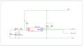
Here is the schematic.Screen Shot 02-02-26 at 06.13 PM.PNG
Screen Shot 02-02-26 at 06.13 PM.PNG
I was have attatched .HEX file to program th PIC12F1840
The accuracy if the 1 hz output depends on the accuracy of the 32768 hz crystal.
The accuracy of the 150 hz output depends on the internal ocillator on the PIC12F1840 whose accuracy is quoted at 1% (10000 PPM)
 

Attachments

trebla

Joined Jun 29, 2019
599
I am using mplabx ide and ipe v.6.05. I get the error when programming the hex code into the pic. Maybe I should say that I am using the pic16f628 instead on the pic16f628A in the IDE and IPE and there may not be a device ID error although I am using the A version?
If you set the project for PIC16F628 device and then try to program a PIC16F628A chip then you get always a device ID warning because the programmer reads the ID from the actual chip and compares it to requested one from project settings. You can ignore the warning in this case because your project does not include features that can be problem with differences between 628 and 628A versions. PIC16F627A, PIC16F628A and PIC16F648A differences are only memory size and the code created for PIC16F627A fits into two other devices without any issue, except the chip ID warning during programming.
 

Thread Starter

Arjune

Joined Jan 6, 2018
354
I have modified the idea from post #125 to run on a PIC12F1840 (An 8 pi PIC.) It works OK om this chip.)
Here is the assembler code.


Code:
;            Program to generate 1 hz anf 150 hz outputs

;
;******************************************************************************************
;
;        OSC      : Internal OSC 4 MHz
;
;******************************************************************************************
        list P=12F1840,ST=OFF,R=DEC
        #INCLUDE  "P12F1840.inc"

       __CONFIG _CONFIG1,  _FOSC_INTOSC & _WDTE_OFF & _PWRTE_OFF &  _MCLRE_OFF & _CP_OFF & _CPD_OFF & _BOREN_OFF & _CLKOUTEN_OFF & _IESO_OFF & _FCMEN_OFF


       __CONFIG _CONFIG2, _WRT_OFF & _PLLEN_OFF & _STVREN_OFF & _BORV_HI & _LVP_OFF


;
;*******************************************************************************
; Pin Assignments
;*******************************************************************************
;
;    PIC signals


; I/O pin use
;    RA0       1 hz out             (Pin 7)         (To pin 4 on programmer connection)
;    RA1       150 hz out         (Pin 6)         (To pin 5 on programmer connection)
;    RA2                     (Pin 5)
;    RA3                  (Pin 4)    NOTE THIS PIN CAN ONLY BE USED AS AN INPUT.
; 
;    RA4     T1OSO             (Pin 3)
;    RA5    T1OSI                  (Pin 2)


;  Define GENERAL PURPOSE RAM AREA (80 bytes maximum)

;*******************************************************************************
; File Register Variables
;*******************************************************************************
;       cblock  0x20


;       endc
;*******************************************************************************
; Common RAM (0x70 to 0x7F)
;*******************************************************************************

Counter        EQU 0x70        ; counter for delay routine in 150 hz code.
W_Temp        EQU 0x71        ;Temporary storage for W during interrupt
STATUS_TEMP    EQU 0x72        ;Temporary storage for STATUS  during interrupt
;
; *****************************

        ORG     0x00
        GOTO    START
        ORG     0x04
        GOTO    ISR
START
; *****************************
;   Initialise+

; *****************************
; Initialise OSC (4MHz, IntOSC)

    banksel    OSCCON              ;  BANK1
        MOVLW   B'11101010'        ; 4 Mhz internal oscillator

;    MOVLW   B'11110010'        ; 8 Mhz internal oscillator

        MOVWF   OSCCON

    BCF    INTCON,GIE        ;All interrupts off

; Initialise I/O port
;select alternate function

    BANKSEL    TRISA            ;  BANK1
;       MOVLW   B'00101100'        ; Bits 0, 4 output Bit  2,  3, 5 input.
        MOVLW   B'00111000'        ; Bits 0, 1, 2 output Bit 3, 4, 5 input.
        MOVWF   TRISA


; Initialized Comparitor.
         banksel 2               ; SET BANK2
           MOVLW   B'00000000'        ; Comparator disabled.
    MOVWF    CM1CON0            ;In bank 2
          banksel 0               ; SET BANK0

    BANKSEL    LATA
    CLRF    LATA        ;Set all outputs low

         banksel 0               ; SET BANK0

; Initialized Timer 1
         banksel 0               ; SET BANK0

    MOVLW    B'10001100'    ;Clock source T1 osc, 1:1 prescale, Dedicated Timer1 oscillator circuit enabled,
                                ;Do not synchronize external clock input, Timer off

    MOVWF    T1CON        ;

    MOVLW    0x00        ;All bits clear (Gate control not used.)
    MOVWF    T1GCON
       BSF     T1CON, TMR1ON    ;Start timer 1            1 cycle

    BANKSEL PIE1
    BSF    PIE1, TMR1IE    ; Enable Timer 1 interrups
        banksel 0               ; SET BANK0

    BSF     INTCON,PEIE
    BSF    INTCON,GIE    ; Enable global interrupts
;       
;       **********
;   Program main
; *****************************
; Main loop


MAIN:
    GOTO Main_program_loop     ;


ISR:    ; assume that it takes 1 cycle to start interrupt code            1 cycle

    BANKSEL PIR1    ;                             1 cycle

        btfss   PIR1, TMR1IF          ;timer interrupt flag    ;         2 cycle
        goto    intDone            ;Not timer1 interrupt

    movlw   0x0C0                   ; For 0.5 second interupts.         1 cycle   
    movwf   TMR1H                   ; Restart the timer                1 cycle

;                            Total of cycles to this point

    bcf     PIR1, TMR1IF            ; Must clear interrupt flag 1 cycle

; Toggle LATA,0
    BANKSEL    LATA
    MOVLW    0x01    ;Set bit 0
    XORWF    LATA
intDone:

    retfie            ;Return from interupt
;
; End of interrupt.


Main_program_loop:
; Toggle LATA,1    ; RA1 (Pin 6)
    BANKSEL LATA    ;            ; 1 cycle
    MOVLW    0x02    ;Set bit 1        ; 1 cycle
    XORWF    LATA    ; Toggle bit        ; 1 cycle
    BANKSEL 0    ; back to bank 0     ; 1 cycle


;Generate 1 cycle of 150 hz
    
Delay_code
    MOVLW    0xFF    ;255        ; 1 cycle
    CALL D_Loop    ;(1030 us)    ; 1030 cycles    (1031 from start)    1034

    MOVLW    0xFF    ;255        ; 1 cycle
    CALL D_Loop    ;(1030us)    ; 1030 cycles    (2062 from start)    1038

    MOVLW    0xFF    ;255        ; 1 cycle
    CALL D_Loop    ;(1030us)    ; 1030 cycles    (3093 from start)

; We need a total of 3333 So we need another 3333- 3093 =  240 cycles.
; So the conter load needs to be ((240 - 6) / 4) - 1) = 233 /4 =  58.25
; So if we make it 58 then we get a delay of ((58 - 1) * 4) + 6 = (57 * 4 ) + 6 = 228 + 6 = 234

;    MOVLW        0x39    ; 57    (Inital calculated value)
    MOVLW        0x3E    ; 62    (Adjusted value)
    CALL    D_Loop    ;(234 us)    ; 1030 cycles    (3327from start)
    GOTO   Main_program_loop    ; 2 cycles
; Subroutines

;Generate 1 cycle of 150 hz
    
D_Loop:
    MOVWF    Counter    ; 1 cycle
L1:    NOP;             1 cycle                      (Loop is 4 cycles)
    DECFSZ   Counter    ; 1 cycle until zero then 2 cycles
    Goto L1        ; 2 cycles
    RETURN            ;2 cycles

;Call to this routine is 2 cycles. Return 2 cycles 2 cycles Initial counter load 111 cycles + 1 extra cycle
; when the counter reaches zero 6 cycles total

;Time is (counter load + 1  * 4) + 6 So if we load the counter with  255 the time will be 1024 + 6 = 1030 cycles

    END                ; End of program
Here is the schematic.View attachment 363053
View attachment 363053
I was have attatched .HEX file to program th PIC12F1840
The accuracy if the 1 hz output depends on the accuracy of the 32768 hz crystal.
The accuracy of the 150 hz output depends on the internal ocillator on the PIC12F1840 whose accuracy is quoted at 1% (10000 PPM)
Thank you very much for your effort. I hope I'm not being a problem but I bought some pic16f15313 8pin mcus from Digikey. I want to connect the 32khz crystal to pin 6 and 7 with corresponding loading capacitors to ground. Is it too much for a request to consider this and provide the code and schematic for this chip? I want to use my mplabx Ide and Ipe and my pickit3 to program it. Sorry for the delay in responding but I was busy with my schizophrenic thoughts trying to understand my environment.
 

LesJones

Joined Jan 8, 2017
4,522
I am not prepared to come up with a plan on how to use the PIC16F15313 to generate 1hz and about 150 hz clocks and then write the software to imlement the plan. Also I do not have any af that device to test. Looking at the Farnell website the PIC12f1840 is only about 50% more expensive than the PIC16F15313.

Les.
 

Thread Starter

Arjune

Joined Jan 6, 2018
354
I am not prepared to come up with a plan on how to use the PIC16F15313 to generate 1hz and about 150 hz clocks and then write the software to imlement the plan. Also I do not have any af that device to test. Looking at the Farnell website the PIC12f1840 is only about 50% more expensive than the PIC16F15313.

Les.
I thought they were all basically the same, only different pin assignments.
 

LesJones

Joined Jan 8, 2017
4,522
Arjune , I have just realised that the original PICKI3 and it's software does not support the PIC12F1840.
I have only just realised this as I have been using PICKTminus software with my PICKIT3 for years. PICKITminus also modifies the firmware in the PICKIT3. (This explains why I could not get my PICKIT3 to work with MPLABx IDE or IPE on either my w7 or W11 systems whe I was trying to simulate the way that you were programing PICs.)
So not buy a PIC12F1840 unless you are prepared to get a PICKIT4 or use your PICKIT3 with PICKIT minus software.
I don't normally use MPLAB. I use MPASM assembler with a different text editor to assemble the program and them PICKITminus to program the device. PICKITminus does have an option to revert the PICKIT3 back to it's original firmware so it can be used with MPLAB again. I have not tried this as I have a PICKIT4 that I use with MPLAB for devices such as the PIC16F18446.
I have not managed to understand why I could not program the PIC16F628A to use the internal 4Mhz oscillator and use timer1 oscillator with a 322768 crystal. It did not write the configuration word correctly. It did work using an external crystal for the sytem clock.

Les.
 
Last edited:

Thread Starter

Arjune

Joined Jan 6, 2018
354
Anyone, how about providing c code for my pic16f15313 for the 1hz output. I can use another one for the ~150hz output.-I don't want this chip to go to waste--wouldn't that be easier than assembly? I'm assuming it would be similar to previous code I used on this site.

There may be a fail safe preventing me from understanding and writing my own code because the Illuminati may gain access to my brain for malicious purposes (such as enabling god to harm the innocent). This may be why I tried to learn the musical keyboard but was unable--or to understand calculus. It was made more difficult than it should have been.
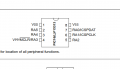
pic16f15313.png
 

Thread Starter

Arjune

Joined Jan 6, 2018
354
Arjune , I have just realised that the original PICKI3 and it's software does not support the PIC12F1840.
I have only just realised this as I have been using PICKTminus software with my PICKIT3 for years. PICKITminus also modifies the firmware in the PICKIT3. (This explains why I could not get my PICKIT3 to work with MPLABx IDE or IPE on either my w& or W11 systems whe I was trying to simulate the way that you were programing PICs.)
So not buy a PIC12F1840 unless you are prepared to get a PICKIT4 or use your PICKIT3 with PICKIT minus software.
I don't normally use MPLAB. I use MPASM assembler with a different text editor to assemble the program and them PICKITminus to program the device. PICKITminus does have an option to revert the PICKIT3 back to it's original firmware so it can be used with MPLAB again. I have not tried this as I have a PICKIT4 that I use with MPLAB for devices such as the PIC16F18446.
I have not managed to understand why I could not program the PIC16F628A to use the internal 4Mhz oscillator and use timer1 oscillator with a 322768 crystal. It did not write the configuration word correctly. It did work using an external crystal for the sytem clock.

Les.
I don't know what is picktminus. I don't want to change to pickit 4-besides I don't want to spend additional money. I don't know what is the system clock-do you disable the internal oscillator, is this the system clock? May I ask what is your occupation? I am unemployed. Is there an online electronics job that you know that I can do at home on my computer with a couple of hours per day?
 

LesJones

Joined Jan 8, 2017
4,522
PICKITminus is a program that works with a PICKIT2 or PICKIT3. To use it it is almost identical with the PICKIT3 software that is supplied with the PICKIT3. If you type "PICKITminus" into a search engine (Such as google.) you wil find more information about it.
I was a computer engineer before I retired but it did not involve anything to do with PIC chips. I first learned about them from projects in Practical Electronics and Elector magazines.

Les.
 

Thread Starter

Arjune

Joined Jan 6, 2018
354
// PIC16F15313 Configuration Bit Settings
// 'C' source line config statements

// CONFIG
#pragma config FOSC = HS // Oscillator Selection bits (HS oscillator: High-speed crystal/resonator on RA6/OSC2/CLKOUT and RA7/OSC1/CLKIN)
#pragma config WDTE = OFF // Watchdog Timer Enable bit (WDT disabled)
#pragma config PWRTE = ON // Power-up Timer Enable bit (PWRT enabled)
#pragma config MCLRE = OFF // RA5/MCLR/VPP Pin Function Select bit (RA5/MCLR/VPP pin function is digital input, MCLR internally tied to VDD)
#pragma config BOREN = ON // Brown-out Detect Enable bit (BOD enabled)
#pragma config LVP = OFF // Low-Voltage Programming Enable bit (RB4/PGM pin has digital I/O function, HV on MCLR must be used for programming)
#pragma config CPD = ON // Data EE Memory Code Protection bit (Data memory code-protected)
#pragma config CP = ON // Flash Program Memory Code Protection bit (0000h to 03FFh code-protected)

// #pragma config statements should precede project file includes.
// Use project enums instead of #define for ON and OFF.

#include <xc.h>
#include <stdint.h>

#define _XTAL_FREQ 16000000

#define ONE_HZ_PIN PORTBbits.RB0
#define OHF_HZ_PIN PORTBbits.RB3

volatile uint16_t s1 = 0;
volatile uint8_t s2 = 0;
volatile uint8_t one_Hz_flag = 0;
volatile uint8_t ohf_Hz_flag = 0;

const uint8_t tmr1_h = 254;
const uint8_t tmr1_l = 112;

/*
*
*/
void mcu_Init(void)
{
CMCONbits.CM = 0b111;
PORTA = 0xFF;
PORTB = 0xFF;

TRISA = 0x00;
TRISB = 0x00;
}

/*
* http://eng-serve.com/pic/pic_timer.html
*/
void isr_Init(void)
{
//Timer1 Registers Prescaler= 1 - TMR1 Preset = 65136 - Freq = 10000.00 Hz - Period = 0.000100 seconds
T1CONbits.T1CKPS1 = 0b0; // bits 5-4 Prescaler Rate Select bits
T1CONbits.T1CKPS0 = 0b0; // bit 4
T1CONbits.T1OSCEN = 0b1; // bit 3 Timer1 Oscillator Enable Control bit 1 = on
T1CONbits.nT1SYNC = 0b1; // bit 2 Timer1 External Clock Input Synchronization Control bit...1 = Do not synchronize external clock input
T1CONbits.TMR1CS = 0b0; // bit 1 Timer1 Clock Source Select bit...0 = Internal clock (FOSC/4)
T1CONbits.TMR1ON = 0b1; // bit 0 enables timer
TMR1H = tmr1_h; // preset for timer1 MSB register
TMR1L = tmr1_l; // preset for timer1 LSB register

// Interrupt Registers
INTCON = 0; // clear the interrpt control register
INTCONbits.TMR0IE = 0b0; // bit5 TMR0 Overflow Interrupt Enable bit...0 = Disables the TMR0 interrupt
PIR1bits.TMR1IF = 0b0; // clear timer1 interupt flag TMR1IF
PIE1bits.TMR1IE = 0b1; // enable Timer1 interrupts
INTCONbits.TMR0IF = 0b0; // bit2 clear timer 0 interrupt flag
INTCONbits.GIE = 0b1; // bit7 global interrupt enable
INTCONbits.PEIE = 0b1; // bit6 Peripheral Interrupt Enable bit...1 = Enables all unmasked peripheral interrupts
}

/*
*
*/
void main(void)
{
mcu_Init();
isr_Init();

while(1)
{
if(one_Hz_flag == 1)
{
ONE_HZ_PIN ^= 0b1;
one_Hz_flag = 0;
}
if(ohf_Hz_flag == 1)
{
OHF_HZ_PIN ^= 0b1;
ohf_Hz_flag = 0;
}
}
}

/*
* http://eng-serve.com/pic/pic_timer.html
*/
void __interrupt() ISR(void)
{
// Timer1 Interrupt - Freq = 10000.00 Hz - Period = 0.000100 seconds
if(PIR1bits.TMR1IF == 0b1) // timer 1 interrupt flag
{
if(s1++ > 4200)
{
one_Hz_flag = 1;
s1 = 0;
}

if(s2++ > 26)
{
NOP();
NOP();
NOP();
ohf_Hz_flag = 1;
s2 = 0;
}

PIR1bits.TMR1IF = 0b0; // interrupt must be cleared by software
PIE1bits.TMR1IE = 0b1; // reenable the interrupt
TMR1H = tmr1_h; // preset for timer1 MSB register
TMR1L = tmr1_l; // preset for timer1 LSB register
}
}
/*----------------------------------------------------------------------------*/

I got this program from post #31. Can someone modify it to use with my PIC16F15313 chips with a 32khz crystal as the secondary oscillator.
 
Last edited:

LesJones

Joined Jan 8, 2017
4,522
When you chose the PIC16F15313 did you check that you could program it using MPLAB and the PICKIT3 ?
If you can't program it there is no point in anyone writing code to run on the PIC16F15313.
Also the normal 16 Mhz crystal will probably only be accurate to about 20 PPM and you said that you want 0.2 PPM .
Les.
 

drjohsmith

Joined Dec 13, 2021
1,630
// PIC16F15313 Configuration Bit Settings
// 'C' source line config statements

// CONFIG
#pragma config FOSC = HS // Oscillator Selection bits (HS oscillator: High-speed crystal/resonator on RA6/OSC2/CLKOUT and RA7/OSC1/CLKIN)
#pragma config WDTE = OFF // Watchdog Timer Enable bit (WDT disabled)
#pragma config PWRTE = ON // Power-up Timer Enable bit (PWRT enabled)
#pragma config MCLRE = OFF // RA5/MCLR/VPP Pin Function Select bit (RA5/MCLR/VPP pin function is digital input, MCLR internally tied to VDD)
#pragma config BOREN = ON // Brown-out Detect Enable bit (BOD enabled)
#pragma config LVP = OFF // Low-Voltage Programming Enable bit (RB4/PGM pin has digital I/O function, HV on MCLR must be used for programming)
#pragma config CPD = ON // Data EE Memory Code Protection bit (Data memory code-protected)
#pragma config CP = ON // Flash Program Memory Code Protection bit (0000h to 03FFh code-protected)

// #pragma config statements should precede project file includes.
// Use project enums instead of #define for ON and OFF.

#include <xc.h>
#include <stdint.h>

#define _XTAL_FREQ 16000000

#define ONE_HZ_PIN PORTBbits.RB0
#define OHF_HZ_PIN PORTBbits.RB3

volatile uint16_t s1 = 0;
volatile uint8_t s2 = 0;
volatile uint8_t one_Hz_flag = 0;
volatile uint8_t ohf_Hz_flag = 0;

const uint8_t tmr1_h = 254;
const uint8_t tmr1_l = 112;

/*
*
*/
void mcu_Init(void)
{
CMCONbits.CM = 0b111;
PORTA = 0xFF;
PORTB = 0xFF;

TRISA = 0x00;
TRISB = 0x00;
}

/*
* http://eng-serve.com/pic/pic_timer.html
*/
void isr_Init(void)
{
//Timer1 Registers Prescaler= 1 - TMR1 Preset = 65136 - Freq = 10000.00 Hz - Period = 0.000100 seconds
T1CONbits.T1CKPS1 = 0b0; // bits 5-4 Prescaler Rate Select bits
T1CONbits.T1CKPS0 = 0b0; // bit 4
T1CONbits.T1OSCEN = 0b1; // bit 3 Timer1 Oscillator Enable Control bit 1 = on
T1CONbits.nT1SYNC = 0b1; // bit 2 Timer1 External Clock Input Synchronization Control bit...1 = Do not synchronize external clock input
T1CONbits.TMR1CS = 0b0; // bit 1 Timer1 Clock Source Select bit...0 = Internal clock (FOSC/4)
T1CONbits.TMR1ON = 0b1; // bit 0 enables timer
TMR1H = tmr1_h; // preset for timer1 MSB register
TMR1L = tmr1_l; // preset for timer1 LSB register

// Interrupt Registers
INTCON = 0; // clear the interrpt control register
INTCONbits.TMR0IE = 0b0; // bit5 TMR0 Overflow Interrupt Enable bit...0 = Disables the TMR0 interrupt
PIR1bits.TMR1IF = 0b0; // clear timer1 interupt flag TMR1IF
PIE1bits.TMR1IE = 0b1; // enable Timer1 interrupts
INTCONbits.TMR0IF = 0b0; // bit2 clear timer 0 interrupt flag
INTCONbits.GIE = 0b1; // bit7 global interrupt enable
INTCONbits.PEIE = 0b1; // bit6 Peripheral Interrupt Enable bit...1 = Enables all unmasked peripheral interrupts
}

/*
*
*/
void main(void)
{
mcu_Init();
isr_Init();

while(1)
{
if(one_Hz_flag == 1)
{
ONE_HZ_PIN ^= 0b1;
one_Hz_flag = 0;
}
if(ohf_Hz_flag == 1)
{
OHF_HZ_PIN ^= 0b1;
ohf_Hz_flag = 0;
}
}
}

/*
* http://eng-serve.com/pic/pic_timer.html
*/
void __interrupt() ISR(void)
{
// Timer1 Interrupt - Freq = 10000.00 Hz - Period = 0.000100 seconds
if(PIR1bits.TMR1IF == 0b1) // timer 1 interrupt flag
{
if(s1++ > 4200)
{
one_Hz_flag = 1;
s1 = 0;
}

if(s2++ > 26)
{
NOP();
NOP();
NOP();
ohf_Hz_flag = 1;
s2 = 0;
}

PIR1bits.TMR1IF = 0b0; // interrupt must be cleared by software
PIE1bits.TMR1IE = 0b1; // reenable the interrupt
TMR1H = tmr1_h; // preset for timer1 MSB register
TMR1L = tmr1_l; // preset for timer1 LSB register
}
}
/*----------------------------------------------------------------------------*/

I got this program from post #31. Can someone modify it to use with my PIC16F15313 chips.
what have you tried ?
why are you changing pic ?
 

Thread Starter

Arjune

Joined Jan 6, 2018
354
what have you tried ?
why are you changing pic ?
I haven't tried anything because I don't know what to do. I changed pic because is was cheap and my pic16f628a had device ID faults. I anticipate further errors when attempting to program them.
 
Top