Advice wanted for measurement of low ohm coils with microcontroller ADC. Negative voltage protection needed.

Thread Starter

farm_tinker

Joined Nov 20, 2025
37
Wasn't sure if this belonged in Power Electronics, Sensor Design, or here. Please move if I put this in the wrong forum.

I'm puzzling over how to measure my load resistance in this part of my circuit:
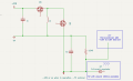
1790797713258.png

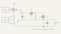
in the above schematic is a SMPS that produces up to -10V or so while in operation. Control lines and most of the rest of the circuitry is omitted. When the the SMPS is not in operation, I need to be able to take a reading on the load and determine its resistance for power calculation.

I'm leaning towards a LM1117 (low dropout LM117) or similar IC setup as a constant current source of around 50mA. I might be better off with a pnp/diode current source, not sure what the prevailing wisdom is on this.

(I've also looked at the LT3092 as a current source but I don't like the price tag of that chip. Not that the price of individual chips really matters for this design as I'll likely only ever make a few.)

Basically, I want to inject a few mA on the side of the coil opposite ground when the SMPS is not running. Then, I'll take an ADC measurement on the voltage to get the resistance of the coil. This would be a short duration event, on the order of a few hundred microseconds. My ADC has a gain amplifier and also does differential measurements. While I'm hoping to avoid differential, using some gain shouldn't be a lot of trouble and should get me the accuracy I need. Hoping for 0.05ohm precision but .1ohm is probably just fine.

I have a budget of 5V and 100mA for the current source. I'm looking at source and not sink as the coil will have a load of several amps in operation and isolating it from ground probably isn't practical. I want to be able to turn off the test current when not in use. What sort of circuit/IC should I be looking at for this?

As for the ADC, it will tolerate exposure to voltages from -0.5V to 5.5V. If I understand this correctly, the 0.7V drop of a signal diode will prevent me from measuring the low voltage produced by my current source and load. How can I protect my microcontroller and still take an accurate reading?
 

panic mode

Joined Oct 10, 2011
5,427
what is the resistance range you wish to measure. inductors that handle few amp in operation, specially for circuit where nominal voltage is 7V, will have tiny resistance. your tolerance may be wider than range.to measure low resistance it is common to use CC source (or sink) and measure voltage drop. but for coils with fraction of an ohm resistance, voltage drop will be tiny which can be solved by adding an amplifier. also you can shift the value to range your ADC is ok with (and stays protected). since the load is an inductor, you would want the current to settle (no oscillation). you mention that you would want current source rather than current sink but that means your negative rail will need to temporarily become positive. that is a problem if you only have inductor, capacitor and fraction of a millisecond to get the value to settle to take the measurement. using cc sink would minimize the problem. btw why stop to take the measurement? can you not measure it in operation? what is the frequency?
 

Reloadron

Joined Jan 15, 2015
7,977
The problem with measuring low resistances is high currents are needed. I see where you mention a PGA (Programmable Gain Amplifier) for your A to D and assume an ADC like maybe an ADS1115 or similar which should be fine for the low voltages you will get using 100 mA with a low resistance. Should you be using an ADS1115 A/D you can set the programmable gain to 16:
ads.setGain(GAIN_SIXTEEN); // +/- 0.256V 1 bit = 0.0078125mV
That gives you +/- 256 mV full scale. While you can use a differential input I see no need since what you read will not be a negative number. You can build or buy your current source. Personally for measuring low resistances I would build a simple circuit like this one or similar. I would not use a low current so as to get a larger voltage drop across your unknown low resistance load. More example can be found here.

Ron
 
Last edited:

Thread Starter

farm_tinker

Joined Nov 20, 2025
37
Ideally I'll be able to measure from 2.5 to 0.25ohm. Nominal load resistance of 1.5ohm.

I'm not measuring the L1 resistance, it's a fixed value.

The load isn't really inductive, it's a heating coil. It can be viewed as a pure resistive load.

The SMPS has a frequency of 300kHz. When the SMPS is on, I'll be reading voltage through a divider and using it as feedback. Power is user selectable.

At 300kHz, I don't have time to do anything other than check the ADC result and adjust the duty. System clock is only 20mHz.

So, I would like to know the resistance of my load before running the SMPS so I can calculate the target voltage. Load resistance doesn't change during a run. Short and open can be checked for without any trouble.

Most of the time, the SMPS is not running and will have a timeout of less than 10sec. So, taking measurements while not running is not a problem.

Maybe I could just slowly pulse the system and read voltage before running at full strength? Might have to verify measurements experimentally. Would save some pins and components.
 

Thread Starter

farm_tinker

Joined Nov 20, 2025
37
The problem with measuring low resistances is high currents are needed. I see where you mention a PGA (Programmable Gain Amplifier) for your A to D and assume an ADC like maybe an ADS1115 or similar which should be fine for the low voltages you will get using 100 mA with a low resistance. Should you be using an ADS1115 A/D you can set the programmable gain to 16:
ads.setGain(GAIN_SIXTEEN); // +/- 0.256V 1 bit = 0.0078125mV
That gives you +/- 256 mV full scale. While you can use a differential input I see no need since what you read will not be a negative number. You can build or buy your current source. Personally for measuring low resistances I would build a simple circuit like this one or similar. I would not use a low current so as to get a larger voltage drop across your unknown low resistance load. More example can be found here.

Ron
It's the ADC0 on an ATtiny 3224. 12bit+ (oversampling/accumulation can give you 17bit), PGA up to 16x, several internal bandgap reference voltages, 375 ksps, other bells and whistles. Pretty fancy tool on such a cheap chip.

I've actually got the ADC overclocked to 615 ksps. I have a compensation function that corrects the readings at that speed.

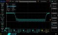
Fun scope shots, high impedance source (500k pot right in the middle on 5V):

ATtiny 3224 ADC overclock 500k pot wide.jpg

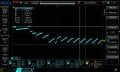
Tighter view:

ATtiny 3224 ADC overclock 500k pot close.jpg

That sawtooth is on the input pin of the ADC when reading 2.5V from the 500k ohm pot. I.E. that's the internal cap charging for ADC reads. I thought it was neato to actually see impedance. (Actual readings will be taken from a much lower impedance but I was poking the machine to understand it).

I've got nice tight controllable pwm including deadtime. 313kHz. Minimum deadtime of 50ns, with increments of 50ns (20MHz clock). 3%-96% duty, period has a resolution of 60ish in 50ns steps.

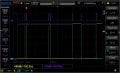
Here's startup of drive and rectifier pulses:

startup square.jpg

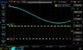
I've got about a 1.6us response time to changes:

buffered_PWM_compensated_ADC_2V_set.jpg

The ATtiny 2 line has programmable logic and event channels with asynchronous capabilities that are quite interesting. All my CPU is doing when generating squares is reading the ADC sample and making a change to my drive width, the logic handles everything else automatically.

Anyhow. I guess writing the problem down got my subconscious churning. Kind of a "well duh." I'll just fire off the pwm with a minimal duty and see what I get for voltage. That will save a couple of pins and no extra components needed. After some testing, I'll have a low power measurement routine that will give me my resistance.

I've already got an enable signal going for my 5V regulator and gate driver that I can also use for this:
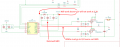
1790858258810.png

Still wrapping my head around the whole negative voltage thing. Now I just need to figure my divider resistance.
 

ronsimpson

Joined Oct 7, 2019
4,857
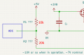
IF Vout = -10V, there will be 10V across R2 and 5V across R1, ADC=0V
If Vout = 0V, there will be 5V across R1&R2, ADC=5V x (2/3) =3.333V
1790861210858.png
Q4 should be an NPN. There will be a 0.6V drop from Base to Emitter, that will change with temperature.
 

MisterBill2

Joined Jan 23, 2018
28,511
REALLY, the biggest challenge of measuring low resistances that I have come across is the resistance of all the other wires involved.
The scheme that works to know the resistance of some part of a circuit is to know the current thru that resistance, and then to measure ONLY the voltage across that resistance. Simple to state, often a challenge to do it.
For this application it is important to understand that "one terminal" measuring is not valid. It does not work for voltage nor current, and certainly not for resistance.
 
Last edited:

BobTPH

Joined Jun 5, 2013
11,666
I must be missing something. It sounds to me like you are trying to measure the resistance of the coil used in an SMPS as a part of the feedback calculation. But that resistance does not change during operation. Why isn’t it just factored in as a constant?
 

Thread Starter

farm_tinker

Joined Nov 20, 2025
37
Q4 should be an NPN. There will be a 0.6V drop from Base to Emitter, that will change with temperature.
You're correct, otherwise I'd have to switch it with a larger negative voltage. I'll also have to put it under the resistors. Dang negative voltages cooking my noodle.

I'm planning to use lower value resistors, preferably less than 1k, so that I don't have impedance problems when taking a reading at speed.

*Edit, lower value resistors mean I need to be able to switch it off to prevent battery drain when not in use.
 

Thread Starter

farm_tinker

Joined Nov 20, 2025
37
Simple to state, often a challenge to do it.
Yup. That's why I'm going to sidestep the whole thing and just use a low duty cycle and possibly a reduced frequency to generate a voltage across it. Then, I'll use the feedback/divider to measure that voltage and figure my resistance. Given a known low duty pwm, I can experimentally find an equation or make a lookup table that will give me my resistance at a good enough precision.

It sounds to me like you are trying to measure the resistance of the coil used in an SMPS as a part of the feedback calculation.
Not quite.

I'm stubborn, the type of ecig that my wife and I prefer is no longer made, been using it for at least a decade. I've been developing my version of it. The commercial version uses an H-bridge to buck/boost a single lithium cell to deliver up to 50w across 2 ohms.

I'm trying to build an inverting buck boost to do the same thing with fewer components because it's fun, educational, and I might be a masochist.

L1 is the inductor, 6uH or so. The coil/load being referred to is a heating element that doesn't have enough inductance to matter. It's a small air core 'spring' of nichrome and is pretty much a pure resistive load. It doesn't care about negative or positive voltage or how dirty the power is. I just need to have .1w resolution control of it. The resistance of the coil can vary from 0.5ohms to somewhere around 2.0ohms. (I actually need to do some research on the range of resistances so I can replicate the function.)

While the load resistance does change when coils/heating elements are changed, we only actually use 1.6ohm coils.

The idea is:
User sets wattage.
Measure resistance of load.
Calculate voltage required for set wattage at measured load.
Fire SMPS and monitor voltage for power control.
 

ronsimpson

Joined Oct 7, 2019
4,857
The idea is: User sets wattage. Measure resistance of load.
Calculate voltage required for set wattage at measured load.
Fire SMPS and monitor voltage for power control.
I worry that the resistance of the hearing element will change with temperature.
My thought is to measure the current using Hall-Effect and measure the voltage and never think about the resistance.

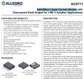
Here is a way to measure current in the heating element. There are many different versions of this type of Hall-Effect Linear Current Sensor. This one adds about 0.001 ohms to the wires. It will hand you a voltage 1.1V for 10A.
1790877603750.png
 

panic mode

Joined Oct 10, 2011
5,427
It will hand you a voltage 1.1V for 10A.
just a small correction...

i have used (and currently use) various products from Allegro ACS7xx range.
note that one can also choose between unipolar and bipolar. unipolar types measure current in one direction only and in this case pay attention to polarity.

output range is from 10 to 90% of the supply voltage.
for example when it is powered from 5V, output range is 0.5V to 4.5V.
that span covers current range. if the current sensing range is bipolar (+/-12.5A for ACS711ELCTR-12AB) then sensitivity is 110mV/A.

note: center of range is center (1/2) of supply
for mentioned product, center of range (from -12.5 to +12.5A) is 0A so for zero current, output would sit at 2.5V (1/2 of 5V supply).
then 10A would make the output change from there by 1.1V (10A * 110mV/A = 1.1V) and therefore it would land at 2.5V+1.1V=3.6V.
when the current is -10A, output would be 2.5V-1.1V = 1.4V.

sorry for edits, i was just trying to make this clear as some of datasheets (like ACS711) do not cover this rather important detail. this is corrected in later products (ACS72x etc)
 
Last edited:

panic mode

Joined Oct 10, 2011
5,427
so IC like this would get you current value directly. it would be expressed as voltage and since current path and sensor part are isolated, common mode problem is solved.
if you do want to find actual resistance (which may be changing with temperature) you also need to measure voltage across load. since that voltage is negative, you can use voltage divider to scale/shift negative voltages to something your ADC can read.
for example:
connect R1 from +5V to your analog input.
connect R2 from your analog input to load (this -10 or -7V nominal)

choose values that work for you. for example R1=10k and R2 = 27 to 47k
suppose R1 is 10k and R2 is 33k. then
when heater voltage is 0V, your ADC would see 3.84V
when heater voltage is -10V, your ADC would see 1.51V
when heater voltage is -15V, your ADC would see 0.35V
 

Thread Starter

farm_tinker

Joined Nov 20, 2025
37
I worry that the resistance of the hearing element will change with temperature.
Nichrome and stainless have positive temperature coefficients. So, if anything, shouldn't my power reduce if heat is substantially effecting the resistance? (Voltage increases as the resistance increases, control reduces duty to compensate.)

Looked it up, nichrome and stainless temp coefficients are .0004/Cdeg and .001/Cdeg, respectively. My thought is that I would watch for a large jump in voltage in either direction to detect a short or open. Might even have guardrails such that if adjusted duty exceeds a tolerance for expected range, it will throw a fault.

My thought is to measure the current using Hall-Effect and measure the voltage and never think about the resistance.
Hall-Effect is interesting. I've always been around them for motor controls and such but they're pretty much a black box and I've never even read up on what the Hall-Effect is. Or who Hall was.

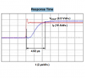
My concern with the Allegro chip is the response time:


1790890912242.png

Just measuring the voltage, I'm at 1.6us. This would put me at 6.22us. Which might not matter, it's not like the load is going to be dynamic much at all. I'll scratch my head on this. It would be easy and interesting.

choose values that work for you. for example R1=10k and R2 = 27 to 47k
suppose R1 is 10k and R2 is 33k. then
when heater voltage is 0V, your ADC would see 3.84V
when heater voltage is -10V, your ADC would see 1.51V
when heater voltage is -15V, your ADC would see 0.35V
I haven't done any math yet or fooled with my schematic. Those ratios probably work but I'm afraid that impedance is going to be too high. I'm looking more at something like R1 of 27ohm and R2 68ohm.

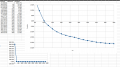
With the overclocked ADC my error curve looks like this with a 100ohm pot set as a 5V divider:

1790892046798.png


Each Sampled measurement in the first column is taken from test runs of 100 reads at 615ksps.

Note that below 1V, my error quickly grows large enough that the results aren't really usable. Ideally I'll adjust the divider ratio such that I don't push into that range. Which shouldn't be a lot of trouble as the voltage is getting pretty high (or low, I guess) at that point.

Anyhow, that's why I want to be able to switch my divider on and off. I need to pump some real current into the divider to be able to accurately measure at that speed.
 

BobTPH

Joined Jun 5, 2013
11,666
I worry that the resistance of the hearing element will change with temperature.
My thought is to measure the current using Hall-Effect and measure the voltage and never think about the resistance.
Exactly. No need to measure resistance, just measure the easier current and voltage. Plus, basing the measurement these thise controls the wattage without worrying about resistance changes.
 

MisterBill2

Joined Jan 23, 2018
28,511
To ACCURATELY measure the voltage across the heater element it is important that none of the load current flows thru the same conductors used for the voltage measurment connection, since that would affect the measured voltage. THAT is the reason for the " Four Wire" connection that some measuring equipment uses.
IN ADDITION, the cost increases with the required accuracy and with the needed resolution. That is often a source of pain in design projects. Besides that, achieveing higher speed measurements is also a serious cost driver.
 
Last edited:

MisterBill2

Joined Jan 23, 2018
28,511
A few more comments: Deciding that we dont need to see other parts of the circuit tells me immediately that you have already decided where the problem is. So why ask us??
OFTEN a statement about the purpose or intent of a design is useful in others recalling a previous experience, and certainly it is usually a courtesy to let us in on what it is all about.

I have not seen much description of just what accuracy is required, or the resolution required for the measurements. An actual statement of the required accuracy is useful.

One bit of information about resistive heating elements: OF COURSE the resistance changes as their temperature changes. That is rather basic to almost all conductive materials. Some materials change much more than others.
 

Thread Starter

farm_tinker

Joined Nov 20, 2025
37
Sorry for the late response. Been real busy.

A few more comments: Deciding that we dont need to see other parts of the circuit tells me immediately that you have already decided where the problem is. So why ask us??
OFTEN a statement about the purpose or intent of a design is useful in others recalling a previous experience, and certainly it is usually a courtesy to let us in on what it is all about.
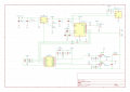
Far be it from me to be discourteous. Full schematic, some component values and switches not added yet, subject of discussion is in B6:
1791799121788.png

I have not seen much description of just what accuracy is required, or the resolution required for the measurements. An actual statement of the required accuracy is useful.
I just need to have .1w resolution control of it. The resistance of the coil can vary from 0.5ohms to somewhere around 2.0ohms.
So, I don't really need a high level of accuracy. Haven't done the math, but .1w resolution is in the neighborhood of .01V. Overclocked, I have .001V resolution from a steady state pot. That .001V resolution comes with the caveat that I have not tried to characterize how accurate that last digit is, I'm assuming that it's at least .005V accurate.

Depending on how I set the ADC, it has up to 17bits of resolution. A lot of those lower bits would just be noise.

One bit of information about resistive heating elements: OF COURSE the resistance changes as their temperature changes. That is rather basic to almost all conductive materials. Some materials change much more than others.
Looked it up, nichrome and stainless temp coefficients are .0004/Cdeg and .001/Cdeg, respectively.
(kanthal is also used but its coefficient is even lower)

https://www.allaboutcircuits.com/textbook/direct-current/chpt-12/temperature-coefficient-resistance/

Under normal operation 334degC is the max temp, with temps of 1000degC being possible when used improperly. The coil is heating a wick saturated in propylene glycol and/or vegetable glycerin. That saturation regulates the temp it actually hits as the vaporization cools the heating element.

Using stainless as it is the coil material with the worst coefficient, "alpha" per degree Celsius is .00094 which is not in the link above. 1.5ohm X (1+0.00094(334-22)) = 1.9399 ohm. Which is a change in resistance of 33% worst case.

Importantly, the resistance is increasing. As I'm regulating voltage to control wattage when operated, an increased resistance results in an increased voltage, feedback then reduces the voltage resulting in decreased wattage. (Which will result in an undershoot that doesn't hurt anything and could be compensated for.)

I.E., unless there is something I'm really not understanding, thermal/voltage runaway isn't going to happen. Wattage drops as temp increases.
 
Top