Advice on wiring a switch

Thread Starter

DavidArthur

Joined Jun 21, 2025
5
Hi,
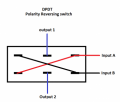
I am trying to figure out how to wire a switch that will basically just swap or reverse wires. I have an outboard motor with a couple of solenoids for an up and down trim. One blue wire controls the up, and a green coming from another solenoid controls the down. The up stopped working so I figured it was the solenoid, replaced it, and it still doesn't work. However, it does work and I can get up and down as long as I swap the wires. I'm thinking it might be something else internal and I just want to get it out on the water. Right now my solution is to route the wires outside of the motor cover and swap them each time for up and down respectively. It would be more convenient if I could figure out some type of switch that could do this. I have a DPDT switch and tried wiring it but didn't have success. Thanks for any help on this!
 
Post #2 is correct wiring, with two serious cautions: First, to use a single switch, it MUST include a center off position AND it must have an adequate current rating for the application load. Two separate requirements.
 
it must have an adequate current rating for the application load.
I had also considered that aspect. The switch must be rated to handle the actuator that raises and lowers the motor. I assumed it is probably 12 volts - and definitely DC - if you can reverse the wiring and that reverses the motor. So the current is the more critical issue.

I made the suggestion and link to a spring loaded switch. One could set it to lower the motor into the water and forget the switch, thus potentially damaging the motor and draining the battery.

EDIT: If the raising and lowering mechanism has limit switches then Center Off and Spring Loading becomes unnecessary.
END EDIT
 
Last edited:

crutschow

Joined Mar 14, 2008
38,690
You could use two SPDT switches if desired, instead of one DPDT with center-off (below):
Note that both switches down, or both up, provide 0V across the load.


1787419510461.png
 
Last edited:
Not for this application.
The solenoids are for trim, so would always need to be turned off when the desired trim is reached.
Even then wouldn't there be limit switches? Attempting to over-trim could result in a jammed motor and possible damage to the motor or even the mechanism. No?
 

crutschow

Joined Mar 14, 2008
38,690
Even then wouldn't there be limit switches? Attempting to over-trim could result in a jammed motor and possible damage to the motor or even the mechanism. No?
Yes.
But I don't see how that is relevant to the request from the TS for a switch connection to control the trim (?).
 

B-JoJo-S

Joined Jan 3, 2026
474
Yes.
But I don't see how that is relevant to the request from the TS for a switch connection to control the trim (?).
True. But it has become a part of the discussion. And now it's fading away from the discussion. There have been many discussions that included extemporaneous warnings that were not a part of the discussion. It's how we roll.
 
The blue and green wires likely trigger the UP and DOWN solenoids rather than powering the motor directly. This relay overview explains the principle.

Use a marine-rated, momentary SPDT ON–OFF–ON switch: fused +12 V to common, blue to one output and green to the other. Since swapping the wires works, first check the original switch and connectors for corrosion or a broken connection.
 
Consider also that the description we are given in post #1 is "rather nebulous", with quite a bit of information missing!
"Solenoids", by themselves, do not do adjusting, unless they drive leadscrews.
Of course, those "solenoids" might actually be contactors switching power to an adjusting motor, or solenoid valves controlling hydraulic cylinders to adjust the motor angle. Unfortunately the word has been used very broadly and that always leads to less accuracy.
 
Top