Facebook
 Google
 GitHub
 Linkedin

Hi,
I tried to modify a +15V/-15V buck/boost module to produce around +10V/-10V output voltage. The operation succeeded but the patient died. I want to try again with a +12V/-12V module that I have. Before I do I'd like to know if there's anything obviously wrong with the method or what might have cause one of the chips to burn.
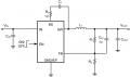
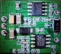
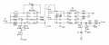
The modules have a CN3903 for the positive output and an MP4560 for the negative output. Each has a resistor divider network that goes to the feedback pin to determine the output. I got the MP4560 working at around -10V, then modified the CN3903 network. Proceeding to test the CN3903 output, the MP4560 started to burn, see "15V bottom.png" of the modified module. Also see the partial schematic of the unmodified module. It's missing the diode and inductor that must be there in each output and some other stuff. It's difficult to get a complete picture.
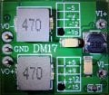
I think it should in principle be possible with reasonably sized resistors between 10k - 100k. As you can see the module sat on unsoldered pins on a breadboard receiving 12V in. Now I suspect that the third inductor is part of a pi-filter to clean up the input voltage. Could it be that intermittent connection of the input supply voltage may have caused inductive spikes in the pi-filter that burnt the MP4560?
I tried to modify a +15V/-15V buck/boost module to produce around +10V/-10V output voltage. The operation succeeded but the patient died. I want to try again with a +12V/-12V module that I have. Before I do I'd like to know if there's anything obviously wrong with the method or what might have cause one of the chips to burn.
The modules have a CN3903 for the positive output and an MP4560 for the negative output. Each has a resistor divider network that goes to the feedback pin to determine the output. I got the MP4560 working at around -10V, then modified the CN3903 network. Proceeding to test the CN3903 output, the MP4560 started to burn, see "15V bottom.png" of the modified module. Also see the partial schematic of the unmodified module. It's missing the diode and inductor that must be there in each output and some other stuff. It's difficult to get a complete picture.
I think it should in principle be possible with reasonably sized resistors between 10k - 100k. As you can see the module sat on unsoldered pins on a breadboard receiving 12V in. Now I suspect that the third inductor is part of a pi-filter to clean up the input voltage. Could it be that intermittent connection of the input supply voltage may have caused inductive spikes in the pi-filter that burnt the MP4560?
Attachments
-
490.8 KB Views: 3
-
919.1 KB Views: 3
-
 633.6 KB Views: 7
 -
 568.6 KB Views: 10
 -
 32.6 KB Views: 11