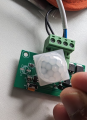
How do I get an LDR to work on this PIR Motion sensor board?

Thread Starter

that_infinte_bum

Joined Aug 11, 2025
34
Update:
I removed the LDR and tested the board with a 1M ohm POT - set the resistance to 1M Ohm (tried with both the 3296W (whose 1MOhm resistor maxed out at .994(994 kΩ) and RM063 whose 1M Ohm resistor maxed out at slightly over 1.005( ≈1.0 MΩ)) - in both cases the PIR sensor wouldn't sense my finger waddling in front of it. Also tried with the POT turned all the way down - same result the PIR sensor wouldn't sense me.

Then, I tested the resistance of the GL5528 LDR on hand. I tested the resistance in absolute darkness, my multimeter couldn't read the LDRs resistance at all. My multimeter has a max Ohm resistance setting of 2M - so when I measured the resistance in my darkened room, the multimeters reading started rising from 0 and after it hit 1.9 the multimeter just started showing 1 - indicating it couldn't measure the resistance any more. This is both surprising and confusing - the documentation I can find on the interwebs says the Dark Resistance of a GL5528 is 1 M Ohm.

Then when I hooked up a 100k Ohm resistor to the LDR (still disconnected from the board) and connected them to the multimeter to measure resistance in the ambient light setting where the unit did work - the resistance was .096 (96 kΩ). I am extremely surprised and dont understand whats happening. Based on this, I set the POT to .100 (100 kΩ) and hooked it up to the units CDS1 point - the PIR sensor did not work.

I have also measured the resistance between the two points where the LDR used to be (CDS1) - and the multimeter shows it has a resistance of 500 kΩ
 
Last edited:

MrChips

Joined Oct 2, 2009
35,018
That is not helpful to anyone reading what you wrote.

Let us take one step at a time.

1) With nothing installed at CDS1, the PIR circuit responds to hand movement?

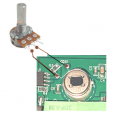
2) You wire a 1MΩ pot to CDS1 using the middle leg and one of the two remaining legs.
With the pot turned all the way counter clock-wise, the PIV does respond?

3) With the pot turned all the way clock-wise, the PIV does respond?

To each question, simply answer Yes or No.
 

MrChips

Joined Oct 2, 2009
35,018
I will be away for the next 24 hours.
Here are the expected results.

1) Yes
2) and 3) one answer is Yes and the other is No.

If that is the case, proceed as follows:

4) If the answer is Yes, adjust the pot until you have to answer No.
Measure the resistance between the centre leg and the unused leg of the pot.

5) If the answer is No, adjust the pot until the answer would be Yes.
Measure the resistance between the centre leg and the unused leg of pot.

6) If you had to do step 4) first, then follow up by doing step 5).

If you did step 5) first, then follow up by doing step 4).

In other words, we are looking for two resistance measurements, one when the PIR just starts working, and one when the PIR just stops working.
 

Thread Starter

that_infinte_bum

Joined Aug 11, 2025
34
That is not helpful to anyone reading what you wrote.

Let us take one step at a time.

1) With nothing installed at CDS1, the PIR circuit responds to hand movement?

2) You wire a 1MΩ pot to CDS1 using the middle leg and one of the two remaining legs.
With the pot turned all the way counter clock-wise, the PIV does respond?

3) With the pot turned all the way clock-wise, the PIV does respond?

To each question, simply answer Yes or No.
I dont understand - Was there something that was unclear? I posted all that I did and my findings. I have tried to edit the post - assuming I wasn't coherent.

1) Yes
2) No
3) No

The pot was wired to CDS1 and the point next to it. As described in Erics photo:
1755578152269.png
 
Last edited:

ericgibbs

Joined Jan 29, 2010
21,531
hi that,
On some PIR modules, it is necessary to wait a few tens of seconds for the unit to stabilise after powering up.

So when you make a change to the ldr/pot settings, wait say 20 secs before trying the hand movement test.
I assume the Fresnel lens is covering the Sensor while you are doing these tests?
E
 

Alec_t

Joined Sep 17, 2013
15,149
Since a PIR detects motion, not a static light level, there will likely be some hand movement speed below which the PIR won't respond. So simply covering the PIR with your hand may not be enough to trigger it.
 

Thread Starter

that_infinte_bum

Joined Aug 11, 2025
34
When I did the tests there was no fresnel lens as my finger was waving right in front of the PIR sensor.

I have since put the fresnel lens back on the sensor and tried with the pot set to 1M and the probes on the solder pads for at least a minute. Turned the pot down all the way with no change in the result.

One thing to note was when I had the LDR on, and during its testing phase when I couldn't get it to work in ambient light - when I power cycled this unit by turning the adapter on/off at the wall, as soon as I would turn the power on, there would be an initial output for a few seconds before the unit "died down". But with the dupont wire pins on the CDS1 solder pads when I power cycle the unit, there is absolutely no output.

Some photos of the ~1M pot and the probes on the unit:
1755678749698.png1755678772751.png
 
Last edited:

MrChips

Joined Oct 2, 2009
35,018
What do you mean by the probes on the solder pads?
Why are you showing us a photo of the DMM?

The DMM must not be connected to the LDR while doing these tests.
 

Thread Starter

that_infinte_bum

Joined Aug 11, 2025
34
What do you mean by the probes on the solder pads?
Why are you showing us a photo of the DMM?

The DMM must not be connected to the LDR while doing these tests.
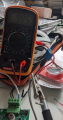
The photo of the multimeter is to show what I set the POT to.
LDR is out of the picture completely. The female side of the dupoint connector is connected to the POT the male side of the dupoint wire points is the one that is on the CDS1 and the point next to it.
 

Thread Starter

that_infinte_bum

Joined Aug 11, 2025
34
With the Fresnel lens in place, how are you getting almost complete darkness at the lens?
Does darkness at the lens matter at all? That was the whole point of introducing the LDR to the circuit - so the motion sensing works only in dusk/twilight/night? Without the LDR the motion sensing unit works - senses motion irrespective of day/night. Fresnel lens only increases the area the motion is sensed in - which is why I initially didn't bother with it while waving my finger right in front of the lens.

From what I gather, I am trying to find the resistance at which the motion senser stops working - so based on this resistance I can go about the LDR that will have that resistance at 10 Lux (dim light around it). The problem at hand is that I can't seem to find the sweet spot where I can say at X resistance the motion sensing works, at Y resistance it doesn't. Have I misunderstood?
 

Alec_t

Joined Sep 17, 2013
15,149
Does darkness at the lens matter at all?
It shouldn't, provided the PIR is sensitive to infra-red wavelengths only. But yours possibly responds to some visible wavelengths also, so the switching threshold might depend on the visible illumination of both PIR and LDR.
 
Last edited:

MrChips

Joined Oct 2, 2009
35,018
Here is my analysis.

1) With nothing connected to the solder pads provided for CDS1, the PIR works, with or without the Fresnel lens. Yes?

We are making the assumption that the CDS1 is intended to disable the unit in daylight.
We don't know the purpose of R5 01E (1 MΩ) resistor.

2) With 1 MΩ placed where the CDS1 should go, the unit stops responding to motion.

This would indicate that the dark resistance of CDS1 has to be greater than 1 MΩ.
If this is the case, then we have to test with a pot that is greater than 1 MΩ, perhaps a 10 MΩ, or test with an LDR that has a dark resistance greater than 10 MΩ.

Also, you need a DMM that can measure resistance greater than 10 MΩ.
 

Thread Starter

that_infinte_bum

Joined Aug 11, 2025
34
Here is my analysis.

1) With nothing connected to the solder pads provided for CDS1, the PIR works, with or without the Fresnel lens. Yes?

We are making the assumption that the CDS1 is intended to disable the unit in daylight.
We don't know the purpose of R5 01E (1 MΩ) resistor.

2) With 1 MΩ placed where the CDS1 should go, the unit stops responding to motion.

This would indicate that the dark resistance of CDS1 has to be greater than 1 MΩ.
If this is the case, then we have to test with a pot that is greater than 1 MΩ, perhaps a 10 MΩ, or test with an LDR that has a dark resistance greater than 10 MΩ.

Also, you need a DMM that can measure resistance greater than 10 MΩ.
It is no longer an assumption. It is proven by the fact that with the LDR on CDS1, the unit only works in absolute darkness.

1. Yes
2. Yes

If I want the PIR to work in twilight wouldn't I need an LDR whose light resistance at ~5 Lux should be greater than 1 MΩ? I dont see any such LDR models on a google search.
 

MrChips

Joined Oct 2, 2009
35,018
We still don't know the threshold resistance for the unit to work under your desired circumstances.
Try a 1 MΩ resistor in series with your LDR (or one with the highest dark resistance).
 

activerfid

Joined May 30, 2020
35
You could deduce the threshold a different way, though you need to be extremely careful, especially if you are new to soldering. Ensure no power is applied. Remove the LDR and R5. Solder one end of the 1M pot to the top of C4 (as far as I can see from the photos this is 0V). Solder the other end of the pot to the bottom of C4 (should be 3V3). Solder the pot wiper to pin 7 of U1 (the bottom pad of CDS1). Set the pot to midway. Check connections have no shorts. Connect DVM (voltage DC) between 0V and the pot wiper. Cover the unit completely (ideally put it back into its case) so there is only a tiny amount of ambient light. Apply power, the DVM should show approximately 1.5V. Adjust the pot slowly, checking that the voltage is decreasing until (with hand waving) the lights come on and note the voltage shown on the DVM. At a guess this will be somewhere around the 0.5V mark. We can then deduce suitable divider resistors, though the internal resistance of the DVM will be a factor.
 

Thread Starter

that_infinte_bum

Joined Aug 11, 2025
34
Update:

I only got 1M pot in the kit, but to test the board with a 2M pot, I used a 1M Ohm resistor in addition to the pot. I did:

  • CDS1 Pad #1 → One end of 1MΩ resistor
  • Other end of 1MΩ resistor → End1 of pot
  • CDS1 Pad #2 → Wiper of pot
  • End2 of pot → leave unconnected

After verifying I actually did have a 2M pot on my DMM, I set about to find out at what exact resistance did the PIR sensor work.
I have now confirmed that at 1010 MΩ the sensor does NOT work. It works at 1012 MΩ (the DMM kept changing the values between 1012, 1013,1014 - but never below 1012).
Now, how do I find an LDR that has 1012 M Ohm resistance at 5 Lux? Or is there another way I can go about this?
 

ericgibbs

Joined Jan 29, 2010
21,531
Hi that,
Have you measured the resistance at which the LDR enables and disables the Light?
If Yes please post the two values, it maybe possible to connect a suitable resistor in series with that LDR.
E
 

activerfid

Joined May 30, 2020
35
In my view, it will be better to determine the voltage required on pin 7 of U1 (with the pot connected as mentioned and the LDR and R5 removed). Presently the current through the divider is far too low (with 10M values) to be reliable (in my opinion) and you would be operating in the far logarithmic end of the response curve, where a small change in light level would result in a substantial resistance change. Once the threshold voltage is known then something like the GL5516 LDR will be better and we can advise the resistor divider values to get a realistic current flow and threshold voltage. We do need to be 100% sure that U1 incorporates LDR response functionality.
 
Top