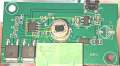
How do I get an LDR to work on this PIR Motion sensor board?

MrChips

Joined Oct 2, 2009
35,018
You don’t have to solder the pot directly to the board.
Get a 1 MΩ pot and connect it to the board using two lengths of insulated hook up wire. Use the centre leg and one other leg. Reduce the resistance of the pot until the unit stops working. Measure the resistance of the pot.
 

Thread Starter

that_infinte_bum

Joined Aug 11, 2025
34
You don’t have to solder the pot directly to the board.
Get a 1 MΩ pot and connect it to the board using two lengths of insulated hook up wire. Use the centre leg and one other leg. Reduce the resistance of the pot until the unit stops working. Measure the resistance of the pot.
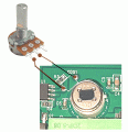
Interesting. Thank you. I have got some dupont jumper wires handy anyway - will buy a 1M Ohm pot tomorrow. What/Where on the board can I connect the potentiometer to?
 

Thread Starter

that_infinte_bum

Joined Aug 11, 2025
34
hi that,
If you have a couple of short wires, 2 or 3 inches long, use them to connect the pot while testing.

If you keep soldering to those PCBs they will peel off !

E
Where do those wires connect on to the PCB? My soldering skills aren't top notch either so I'd rather not de-solder the LDR if I dont have to. Because after measuring the resistance the next step will be to desolder the current LDR and solder the new LDR in.

I will get a 1 M ohm pot, something like this tomorrow. Attach two wires - with at least one to centre - where does the other end go on the circuit board? Can I loop/solder the wires around the LDR's legs? But that would alter the LDRs resistance? No, it will build up on the LDRs resistance? I am confused.
 

MisterBill2

Joined Jan 23, 2018
27,992
LOOKING BACK at the photo in post #1, Why not measure the resistance across the two terminals for the sensor "CDS1", before any more damage is done. It might be shunted by some other resistance on the PCB.
 

ericgibbs

Joined Jan 29, 2010
21,531
Hi
If you take the trouble to check the posted front and back images of the PCB, you can CLEARLY see that there is NO component linking across the LDR pads.
E

Added image showing in Yellow the reverse track, it appears that LDR and IC and PD are powered by a dedicated power supply.
EG 1670.png
 
Last edited:

MrChips

Joined Oct 2, 2009
35,018
So that means I do need to desolder the LDRs. When you mentioned
> If you keep soldering to those PCBs they will peel off
I got an impression that I could somehow test this with the current LDR on.
If you don't want to remove the LDR, cover it with something that is opaque. Black electrical tape works well.
If you don't have black tape, cover it with masking tape or sticky tape, then aluminium foil, then more tape, making sure that the aluminium foil is not exposed thus causing a short circuit.
 

Thread Starter

that_infinte_bum

Joined Aug 11, 2025
34
Update:
I bought a little kit today with some of the bits and bobs I think I will require. I hooked (made a J hook on the resistor's legs and hung it off the LDR legs - kept it tugged while testing) up a 100k Ohm resistor to the LDR and indeed in ambient light the PIR motion sensor works as expected. I'd still want it to work in double the ambient light I tested this unit in. So perhaps a 200k Ohm resistor will be my next step.

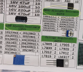
I am going to hook up a pot tomorrow and check for resistance. From the kit I ordered, I see two types of components Adjustable Potentiometer and Adjustable Resistance - do they mean the same thing? I think they do - I tested them with a multimeter and they seem to be varying resistance when I turn the screws that are on the component. But I want to be certain I am choosing the right component. In the photo taken of the box - the Ohm values (numbers inside the brackets) are swapped around

1755257544163.png1755257628981.png
 

bertus

Joined Apr 5, 2008
22,987
Hello,

A potmeter has 3 pins.
An adjustable resistor has likely 2 pins.
A potmeter can be used as an adjustable resistor by using the middle pin and one of the outer pins.

The RM063 are single turn potmeters, the can be turned over an 270 degrees range.
The 3296W are mutliturn potmeters, they can make 25 turns.

Bertus
 

Attachments

Thread Starter

that_infinte_bum

Joined Aug 11, 2025
34
Hello,

A potmeter has 3 pins.
An adjustable resistor has likely 2 pins.
A potmeter can be used as an adjustable resistor by using the middle pin and one of the outer pins.

The RM063 are single turn potmeters, the can be turned over an 270 degrees range.
The 3296W are mutliturn potmeters, they can make 25 turns.

Bertus
Ahh - thank you kindly. I was being gentle and almost hesitant turning the screws - which is why started with a lower capacity pot - even if I break it I will still have the 1M pot.
hi that,
Basically Yes.
Pleased to see you are making progress.:)
E
I am very thankful to all who have replied and helped me progress so far.
 

Thread Starter

that_infinte_bum

Joined Aug 11, 2025
34
I was thinking - a question I should probably have begun with. What completes the circuit in this PIR sensor (which takes an input of 12V DC and outputs 12V DC when it senses motion)?

My understanding is - The IR sensor sensing motion, completes the circuit and the time delay (which looks like a potentiometer) makes the circuit sustain for however long the time delay is set to. This means once the PIR sensor senses motion, it completes the circuit - but if there is an LDR on the circuit - it makes the final call of completing (or not) the circuit depending on the resistance value it has at that time.

So, an LDR in darkness has higher resistance and in bright light has lesser resistance. Higher resistance means less current flow - then how is this circuit completed in the dark? Is there a transistor in one of the chips that reverses this logic? But the counter argument is, even if there is less current flow, the circuit is still complete, no?

Could some one please help me understand this?
 

MrChips

Joined Oct 2, 2009
35,018
I was thinking - a question I should probably have begun with. What completes the circuit in this PIR sensor (which takes an input of 12V DC and outputs 12V DC when it senses motion)?

My understanding is - The IR sensor sensing motion, completes the circuit and the time delay (which looks like a potentiometer) makes the circuit sustain for however long the time delay is set to. This means once the PIR sensor senses motion, it completes the circuit - but if there is an LDR on the circuit - it makes the final call of completing (or not) the circuit depending on the resistance value it has at that time.

So, an LDR in darkness has higher resistance and in bright light has lesser resistance. Higher resistance means less current flow - then how is this circuit completed in the dark? Is there a transistor in one of the chips that reverses this logic? But the counter argument is, even if there is less current flow, the circuit is still complete, no?

Could some one please help me understand this?
No.
Your concept of how circuits operate is very simplistic.
You are applying Ohm’s Law as if it were a resistor. The PIR sensor and the rest of the circuit is not a resistor.

So don’t go this route. You need to learn more about how circuits work.
 

MisterBill2

Joined Jan 23, 2018
27,992
To elaborate on HOW the system senses motion, which is important. The basis of the IR motion detection system is the alternating signal from the IR sensor. The alternating signal, which is the variation of resistance. is created by the IR radiation being interrupted as the person moves, and the path is interrupted by the masking effect of the stripped lens. So any testing will require fairly rapid variations of the light or IR intensity on that sensor. The amplifier responds to low frequencies, not a single change in the IR level.
 

MrChips

Joined Oct 2, 2009
35,018
On the topic of potentiometers, parts 3296W and RM063 in your kit of components are both potentiometers.
It is poor labeling on the part of the kit supplier. Note the gross error in "RM063 Adjustable Resistance 65PCS".

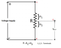
Notice that both components have three terminals. The two outer terminals connect to the ends of a resistor, giving the maximum resistance R. The middle terminal slides along the body of the resistor thus creating two resistors, R = R1 + R2.
Thus one application of a pot is a voltage divider or volume control.

1755261817543.png

The word "potentiometer" comes from the combination of the two words "potential" and "meter". In a basic physics class, students learn how to use a long wire potentiometer in order to measure voltage, i.e. it is a potential meter.

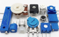
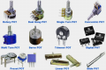
These are all potentiometers.
1755261308840.png

1755261402996.png
 
Top