Motor control via motion sensor activation

Thread Starter

WHI13tan

Joined Feb 28, 2025
2
Hi,

To preface I know basically nothing in terms of specifics about circuitry and electronics. I understand the basic concepts and know what most of the parts and pieces do generally.

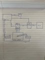
With that being said I am trying to build a simple motor control that will activate off of motion and turn a motor left until a stop point and then to the right until a stop point and keep doing that until the motion sensor times out. So activates off of motion and spins a small nema 17 motor left and right for a short duration of time.

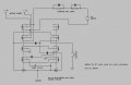
I have been researching different products and applications but man oh man are the options endless. I have seen the adrino/clone boards that you can piece together and program to do what you want which I am not against just trying to see if there is an easier way. I have found the 36820 board and watched a video of them activating via motion sensor as well as using stops with it to stop or change directions. In future I would like to use a 12v motor which I believe I would need to connect the board to another motor controller that can handle the higher voltage.

Is there a better way to do this then what I am going towards right now? Would it be better to start with a raw programable ardrino board and just program the step motor to turn x distance right then stop and turn x distance left until it times out or is using the stops the best action.

If there is a better way I am all ears.

whats your thoughts?

1740779050467.png
 

MisterBill2

Joined Jan 23, 2018
27,159
OK, and welcome to AAC!
What you have is two different functions here. First, switching on a motor control package from a motion sensor, and second, a motor control package that runs a motor back and forth while active.
Now for the questions about the details: How accurately does the control need to be?? Can a sensing switch be added to each stop point? The concept is nothing new, industrial automation has been doing it for 100 years.
The motor control will take two DPDT relays with contacts adequate for the motor current, and coils the same voltage as the motor power. It will also require a SPDT momentary limit switch at each end of the motor motion. One set of contacts on each relay drives it , the other N.O contact latches the relay until the other limit switch releases it.

AND PLEASE!! Nobody draw it with diodes added!! THAT will cause confusion and a serious chance of polarity errors.
 

Thread Starter

WHI13tan

Joined Feb 28, 2025
2
1. motion sensor triggers Adrino
2. Adrino sends power to motor controller starting up the motor
3. motor spins until it hits a contactor
4. contactor opens and Adrino sends signal to dpdt relay to switch polarity of motor
5. motor spins opposite direction
6. motor spins until it hits opposite contactor and sequence reverses
7. action continues until preset time from motion sensor runs out.

Am I seeing/representing this correctly?
 

Attachments

MisterBill2

Joined Jan 23, 2018
27,159
I certainly see no reason to ad an arduino to the system, with it's delicate package and the demand for a regulated low voltage supply. The relays latching and unlatching will assure that the system will default to the off mode when the power is removed. The wiring of the SPDT limit switches is a bit complicated in that each switch must latch one relay while unlatching the other. That is the common two button start/stop scheme slightly re-arranged. And the motor control poles of the relay are the exact duplicate of the classic SPDT DC motor reversing scheme, with the two NC contacts to supply negative and the two NO contacts to the supply positive, and the DC motor between the two "common" relay terminals.
 

Tonyr1084

Joined Sep 24, 2015
9,744
A windshield wiper motor does the same thing but without reversing the motor. AND it has a PARK feature. If mechanical means of direction reversal is undesirable there is an easy way with a 4PDT relay. Actually you'll only need three poles but I've never seen a 3PDT relay.

[edit] OK, yes, I've now found a 3PDT relay. See post #7.
The reason behind use of a windshield wiper motor is because changing the direction of a motor can be hard on it. I wouldn't recommend bang-reversing a motor the way the below circuit does simply because it is hard on the motor. But in accordance with your request, the circuit below is what I came up with.
[end edit]
 
Last edited:

Tonyr1084

Joined Sep 24, 2015
9,744
Took a bit of grey matter but:
In figure 1 when the PIR goes active the motor will rotate the arm away from SW1. It will continue to slew until the arm reaches SW2.
FIGURE 1.png
When SW2 is hit the 4PDT relay will switch on and hold itself on through SW1 because SW1 is closed through C & NC (Normally Closed) leads.
FIGURE 2.png
Figure 2 SW2 has been hit and the relay has become active. It's held active through SW1 until the arm touches SW1. Once SW1 is hit the relay will drop out and the motor will again reverse direction. The process goes on until the PIR times out, at which point the motor will be left in whatever position it was in when the PIR went inactive. Since the relay drops out as well, when the PIR becomes active again the motor will again slew away from SW1 toward SW2 from whatever position it was in when the PIR went inactive.

I used a generic drawing of a PIR. It is in no way meant to represent how you're using YOUR PIR to turn things on and off.

Hope this helps.
 
Last edited:

Tonyr1084

Joined Sep 24, 2015
9,744

Tonyr1084

Joined Sep 24, 2015
9,744
If you're intent on using a stepper motor then my drawing does nothing for your approach. Use of a stepper motor requires more electronics control than the simple approach pictured in post #6.

I've already dominated this thread too much. And this is just about all I can offer, so I'll be quiet for a while now.
 

MisterBill2

Joined Jan 23, 2018
27,159
My description in post #4 assumed a brush type permanent magnet DC motor. Using an actual STEPPER MOTOR will allow instant reversing with no problems at all, since steppers are designed for that sort of service. With a stepper, the motion sensor will simply activate the "Drive enable" input to the stepper driver electronics, while the two limits switches will latch and unlatch a relay controlling the "motor direction" selection input.
What would help a lot is more detail about the application, and what sort of accuracy is required.
 

MaxHeadRoom

Joined Jul 18, 2013
30,557
That circuit delivers instant reversals. My scheme is better and it only requires two relays, AND it can allow the motor to stop.
The one I posted also has two relays, and as the circuit is drawn, is each direction requires one push of the button (flip-flop)!
The motor will stop at each LS reached.
It just requires an addition to make automatic reverse, If needed.
 
Last edited:

Tonyr1084

Joined Sep 24, 2015
9,744
There's a number of things we do not know.

What we do know:
1740779050467.png
Stepper Motor Control Board
Microswitches
Stepper Motor (10.2V)
PIR sensor (12 - 24VDC w/adjustable time delay)

What we don't know:
If there's any gear reduction.
If the TS (Thread Starter - a.k.a. WHI13tan) is willing to take a different direction
If the TS already has the above equipment.

What would be nice to know:
Is the TS locked into the above approach?
TS asks: (post #1) "If there is a better way I am all ears."
Is the TS willing to consider a different approach?
What is the purpose of driving a stepper motor back and forth (or any other kind of motor for that matter). What is the goal?

When you keep secrets you get very limited help. When you're forthcoming with your idea - it's not likely anyone is going to steal your idea and beat you to the market - you're more likely to get valid and useful information.

NONE of the ideas offered thus far can be considered "Better" because we still don't know what goal we're working towards. It's easily agreed upon that a stepper motor is better for back and forth motion than a DC motor. Standard DC motors do not like sudden reversal of direction. This has already been stated.

The TS was last active as of 5:50AM (Mountain Standard Time Zone) today, but has not made any further comments. So we're really not able to move forward without additional information. If the TS still wants our help - we're here. But there's no further use in answering an incomplete question until we know more and know for a more certain and clear goal just what that goal is.
 

MisterBill2

Joined Jan 23, 2018
27,159
First, a stepper motor requires a driver module and a power supply able to supply a fairly steady level of power. So a stepper is quite a bit more complex, AND the driver requires more space.
The very simplest of all would be to use a very simple synchronous motor of the type that will start and run in either direction. That type of motor reverses whenever it runs into a stop. The ones I rescued from a microwave oven were powered directly fro the 120 volt mains. The one for the turntable had a greater reduction than the other one, which simply moved a damper.. THAT would be the ultimate simplest. No electronics, no limit switches, and no relays. Next would be the DC reversible motor and the two DPDT reals with the two SPDT limit switches.
The one MAX describes in post #10 uses two 4PDT relays, several diodes, and an RC device that may be a snubber. AND the limit switches need to carry the rated motor current.
 

Tonyr1084

Joined Sep 24, 2015
9,744
simple synchronous motor
Thought of that too. But we weren't told 120VAC was available. I find it pointless to continue solving a problem for someone who has lost the desire to invest in this thread. They haven't been back since 5:50 AM. While no one can say whether they viewed this thread or not - it seems pointless to continue.

Unwatched!
 

MaxHeadRoom

Joined Jul 18, 2013
30,557
@WHI13tan Looking over post #1 again and watching the video on implementing it, it appears to do every think you want?
The LS etc can be hooked up to the card for exactly the operation you want , If I read correctly?
Why are you hesitant to go with that motor and card ??
 

sghioto

Joined Dec 31, 2017
8,633
@WHI13tan Looking over post #1 again and watching the video on implementing it, it appears to do every think you want?
The LS etc can be hooked up to the card for exactly the operation you want , If I read correctly?
I saw that video and using the Auto mode #4 no limit switches are required. The only problem is getting the PIR module to activate the control board as it needs a manual push of a button for start and stop.
The PIR listed switches a ground to the load (no relay). A circuit will be required to activate the start and stop from this or other PIRs.
 
Last edited:

Tonyr1084

Joined Sep 24, 2015
9,744
Top