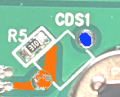
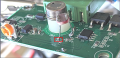
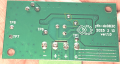
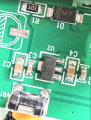
This is my view as well. The LDR and R5 in series is a voltage Divider for the CDS input. I would parallel a 1M pot across R5 and adjust until you trigger at your ambient light level.
Use the variable 1Meg resistor as a rheostat and twiddle it until you detect the circuit switching point at the light level you want. Then measure the resistance. Buy an LDR with a similar resistance at that light level.
Thanks for that. This would be helpful in identifying which LDR I should buy.
Given with what I have in situ - the challenge is getting the motion sensor to work at all - I can alter the light level using a torch et cetera.
I would have thought being able to trace the white lines around R5 and being able to draw/connect from one end to CDS1 and the other end to the other pad - it would mean the resistance is between the LDR legs.
Not quite - I've only got red electrical tape. To simulate darkness I have used my finger, pen's cap - also a double sided black sheet of paper. To simulate light, my LED desk lamp and torch on the phone.
I would have thought being able to trace the white lines around R5 and being able to draw/connect from one end to CDS1 and the other end to the other pad - it would mean the resistance is between the LDR legs.
Hi that,
The White lines are component location points only, not copper tracking.
Refer to the recoloured PCB image I posted, one end of the LDR copper is marked in RED and the other end of the LDR copper is marked in BLUE.
This means the two ends of the LDR are on different copper tracks,
How is the TS attempting to verify the motion sensing function is working?? Without the fresnel lens it is not going to work, and also, with light shining on the IR sensor, it can not possibly work.
Besides that, it may have been destroyed by static electricity while handling it.
Hi that,
The White lines are component location points only, not copper tracking.
Refer to the recoloured PCB image I posted, one end of the LDR copper is marked in RED and the other end of the LDR copper is marked in BLUE.
This means the two ends of the LDR are on different copper tracks,
I understand now. Does that also mean the pad on CDS1 marked in blue just stands alone with no copper tracking to any other component on the board? I wonder that the purpose of CDS1 on this board is then.
If one leg of the LDR goes on to CDS1 - how do I find out where the other leg goes?
How do you map out the copper tracks? Just visual inspection? Or is there a software I can provide this image to that will map out the different copper tracks?
How is the TS attempting to verify the motion sensing function is working?? Without the fresnel lens it is not going to work, and also, with light shining on the IR sensor, it can not possibly work.
Besides that, it may have been destroyed by static electricity while handling it.
A fresnel lens is only required to expand the field/width of sensing for the PIR sensor - if I wave my finger around close enough to the sensor, it works alright - rather worked alright before the LDR was soldered on.
I doubt light shining on the PIR sensor will make any difference to its working (because the PIR sensor is not affected by light - the exact problem that I am trying to solve) PIR sensors detect changes in infrared radiation, which is heat, not visible light. Besides, since I have a torch, I am able to directly shine the light on the LDR without much of it falling on the PIR sensor - I am pretty sure the amount of torch light shining on the IR lens is not that significant to affect its working.
A fresnel lens is only required to expand the field/width of sensing for the PIR sensor - if I wave my finger around close enough to the sensor, it works alright - rather worked alright before the LDR was soldered on.
I doubt light shining on the PIR sensor will make any difference to its working (because the PIR sensor is not affected by light - the exact problem that I am trying to solve) PIR sensors detect changes in infrared radiation, which is heat, not visible light. Besides, since I have a torch, I am able to directly shine the light on the LDR without much of it falling on the PIR sensor - I am pretty sure the amount of torch light shining on the IR lens is not that significant to affect its working.
You don't need to shine light on the LDR. Just the opposite. You need no light on the LDR to make it reach its maximum resistance.
With the LDR removed, the unit works, correct?
1) What is the purpose of the 1 MΩ resistor R5 and how it is connected to the LDR?
2) What is the purpose of the 1 MΩ trim potentiometer VR1? (Don't try to adjust it just yet!)
3) What is the part number and purpose of the 8-pin IC U1?
4) What is the appropriate light vs resistance characteristics required for CDS1?
Presumably, VR1 is used to set a threshold.
Before you adjust it, make sure that you take a resistance of it out-of-circuit so that you can set it back to its original setting if this is required. (Two pins are bridged and hence it is used as a variable resistor.)
If we knew how R5, VR1, CDS1, and U1 are interconnected, we could possibly figure out all of the above.
1) What is the purpose of the 1 MΩ resistor R5 and how it is connected to the LDR?
2) What is the purpose of the 1 MΩ trim potentiometer VR1? (Don't try to adjust it just yet!)
3) What is the part number and purpose of the 8-pin IC U1?
4) What is the appropriate light vs resistance characteristics required for CDS1?
Presumably, VR1 is used to set a threshold.
Before you adjust it, make sure that you take a resistance of it out-of-circuit so that you can set it back to its original setting if this is required. (Two pins are bridged and hence it is used as a variable resistor.)
If we knew how R5, VR1, CDS1, and U1 are interconnected, we could possibly figure out all of the above.
1) I dont know.
2) VR1 is a pot that reflects time delay - in other words, I can set the LED strip lights to be on from 1 to 10 minutes depending on how I set it.
3) There is no part number on the IC U1.
You don't need to shine light on the LDR. Just the opposite. You need no light on the LDR to make it reach its maximum resistance.
With the LDR removed, the unit works, correct?
Apologies to all - I kept referring to shining the light incorrectly. When working on this board during the day, I didn't need to shine the torch at all - other than when testing if the LDRs resistance changed at all. When working in the night, I had to shine the torch on my multimeter whose backlight is broken.
Well, I feel embarrassed now. Sorry for wasting everyone's time. The good news is the LDR does work.
As many members suggested I should have first tested what resistance of an LDR I was after - but being an absolute newbie I just had to work with what I had ordered based on StupidGpt. Other than soldering on/off the LDR a few times I did nothing different to what I have posted so for. When MrChips asked if I had used a black electrical tape, I figured I am just going to test this thing in pitch dark. Shining a very low LED light on to the multimeter's screen which was as far as it can be from the unit - Just as I did this, the unit worked. To test it in my work area, I need to turn off the lights (ambient light still sneaks in) and put a sturdy pen's cap over the LDR. All in all, the model of the LDR I used, GL5528, was the problem.
I think from here on - to get the motion sensing to work in ambient light or pitch dark the options I have available are:
1) Use a different LDR - What LDR model can I use given the situation so far?
2) I am also thinking if I solder on an additional 100 kΩ resistor where the LDRs legs are soldered on (so LDR and resistor in parallel), that should help?
I am an absolute beginner and dont want to risk soldering on a pot to finding out the exact level of GLDR model required - identifying where to solder a pot, if it doesn't work, troubleshooting it - while it sounds educating and fun - I feel I will get frustrated.

 Facebook
 Google
 GitHub
 Linkedin