How do I get an LDR to work on this PIR Motion sensor board?

ericgibbs

Joined Jan 29, 2010
21,527
hi act,
On post #48 I traced the back track of the PCB.
The bottom end of the 1MR is connected to 0V/Common and the top end to the lower end of the LDR.
I would say the 1MR is just used as a 'pull down' to 0V of the IC's Light sense pin, when the LDR is not connected.

E
 

activerfid

Joined May 30, 2020
33
When the LDR is fitted the 1M resistor becomes part of the divider which determines the voltage on pin 7 of U1 and also controls the overall current through the LDR and available for pin 7 of U1. The resistor would be changed to suit a new LDR when the threshold voltage has been determined and we can confirm that the LDR function on U1 is working properly.
 

MrChips

Joined Oct 2, 2009
35,012
What we don’t know and not given in the user manual is the internal resistance of the XL830L DMM in voltage measurement mode.
 

activerfid

Joined May 30, 2020
33
True, and that will be an influencing factor, but you have to start somewhere and removing the LDR and 1M divider resistor and then determining the threshold voltage will help, otherwise you just go round in circles (in my opinion).
 

MrChips

Joined Oct 2, 2009
35,012
A low cost DMM might have internal resistance of 1 MΩ which is not suitable for this measurement.

You need a DMM with internal resistance of 10 MΩ or higher.
Even with 10 MΩ internal resistance, a DVM measuring voltage across a 1 MΩ circuit will have a 10% error.
 

Thread Starter

that_infinte_bum

Joined Aug 11, 2025
34
Hi that,
Have you measured the resistance at which the LDR enables and disables the Light?
If Yes please post the two values, it maybe possible to connect a suitable resistor in series with that LDR.
E
LDR enables the motion senser to work in pitch darkness - the resistance is not measurable by my DMM which can measure a max of 2M ohm.
I did achieve the motion senser to work in very dim light when I had connected a 100k resistor in parallel to the LDR - as mentioned in a previous post. But I want it to work in slightly more light.
 

MrChips

Joined Oct 2, 2009
35,012
LDR enables the motion senser to work in pitch darkness - the resistance is not measurable by my DMM which can measure a max of 2M ohm.
I did achieve the motion senser to work in very dim light when I had connected a 100k resistor in parallel to the LDR - as mentioned in a previous post. But I want it to work in slightly more light.
That makes no sense.
Did you mean to say “when I had connected a 100k resistor in series with the LDR”?
 

Thread Starter

that_infinte_bum

Joined Aug 11, 2025
34
That makes no sense.
Did you mean to say “when I had connected a 100k resistor in series with the LDR”?
No. They are in parallel as mentioned in post #53

....
I bought a little kit today with some of the bits and bobs I think I will require. I hooked (made a J hook on the resistor's legs and hung it off the LDR legs - kept it tugged while testing) up a 100k Ohm resistor to the LDR and indeed in ambient light the PIR motion sensor works as expected. I'd still want it to work in double the ambient light I tested this unit in. So perhaps a 200k Ohm resistor will be my next step.
...
 

Thread Starter

that_infinte_bum

Joined Aug 11, 2025
34
You could deduce the threshold a different way, though you need to be extremely careful, especially if you are new to soldering. Ensure no power is applied. Remove the LDR and R5. Solder one end of the 1M pot to the top of C4 (as far as I can see from the photos this is 0V). Solder the other end of the pot to the bottom of C4 (should be 3V3). Solder the pot wiper to pin 7 of U1 (the bottom pad of CDS1). Set the pot to midway. Check connections have no shorts. Connect DVM (voltage DC) between 0V and the pot wiper. Cover the unit completely (ideally put it back into its case) so there is only a tiny amount of ambient light. Apply power, the DVM should show approximately 1.5V. Adjust the pot slowly, checking that the voltage is decreasing until (with hand waving) the lights come on and note the voltage shown on the DVM. At a guess this will be somewhere around the 0.5V mark. We can then deduce suitable divider resistors, though the internal resistance of the DVM will be a factor.
I am slightly hesitant to desolder R5 as its very tiny and I highly doubt if I will be able to solder it back on again.

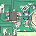
Is pin 7 the one circled in purple or pink?
1756171671250.png

As a hypothetical, say I go ahead with de-soldering R5 and I find out at 500k Ohms the voltage is at 0.5V - what would be the next steps? Would one of those steps be to re-solder R5?
 

MrChips

Joined Oct 2, 2009
35,012
I hate to say this, but something is definitely wrong.
In all your previous tests, you demonstrated that a resistance of 1 MΩ and lower caused the unit to stop working.
Then how can it work with 100 kΩ in parallel?
 

MrChips

Joined Oct 2, 2009
35,012
You need to determine the internal resistance of your DMM when in voltage measurement mode.

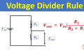
Take two 1 MΩ resistors and connect them in series with a battery.
Measure the voltage across the battery with your DVM.
Measure the voltage across one resistor with your DVM.
From your readings we can calculate the internal resistance of the volt meter.

Like this, where R1 = R2 = 1 MΩ

1756172436838.png
 
Top