How do I adapt twin coil control to control single coil

Thread Starter

Brucey30

Joined Jul 3, 2017
36
No. Then the control of the one coil switch machine will not work. It is designed for use with AC power only.

The diodes provide power for half of the AC cycle. In order to change polarity for half of the AC cycle by using the diodes.
Ok. Now I have better understanding of the circuit. Ty
 

Alec_t

Joined Sep 17, 2013
15,132
What value cap to use
Several hundred microfarads. Start with, say, 220uF. The higher the value the less noticeable the buzz will be, but the higher the average voltage the coil will see. The cap working voltage rating should be >30V. Make sure you get the cap polarity correct!
 

Fcathers72

Joined Sep 7, 2016
14
this has to do model railroad switches (turnout). I have a switch on a panel and it has 3 wires for 2 coils. I the turnout has 2 coils. Energizing on coil turn left. Energizing on the other coil turn right. Works fine. BUT the diffident company railroad turnout I want to use has only 1 coil. And changing the rails left or right by changing the coils polarity by the 2 wires and using same company's controls. I do not want to use company's same controls as maker of turnouts.
I'm thinking there should be a way via diodes or relays this can be done. Note: the coils ONLY get momentarily energized in order to move the rails. How do I do this?
Arnold 7220 turnout controls. ( Want to use)
KATO Uni-Track turnouts I'm using

Thank you
The simplest is a DPDT switch that is mon-off-mon. (3 position). Run power and return to the center terminals. Cross connect the top and bottom terminals then connect to switch machine. Like reversing a D.C. motor. Use aux contacts on switch machine to drive leds placed by the switch so you know which way it is operated
 

djsfantasi

Joined Apr 11, 2010
9,237
The simplest is a DPDT switch that is mon-off-mon. (3 position). Run power and return to the center terminals. Cross connect the top and bottom terminals then connect to switch machine. Like reversing a D.C. motor. Use aux contacts on switch machine to drive leds placed by the switch so you know which way it is operated
Does this work with coils that run off AC?
 

Thread Starter

Brucey30

Joined Jul 3, 2017
36
Several hundred microfarads. Start with, say, 220uF. The higher the value the less noticeable the buzz will be, but the higher the average voltage the coil will see. The cap working voltage rating should be >30V. Make sure you get the cap polarity correct!
Thank You
 

Thread Starter

Brucey30

Joined Jul 3, 2017
36
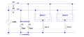
So, use the 14VAC and wire it like this to your Arnold push-buttons :
View attachment 130467
Diodes D1 and D2 can be 1N400x series.
(You can ignore the ground symbol: it's there for simulation purposes).
Question. With the same momentary switch you showed in post 40 ( that's my
So, use the 14VAC and wire it like this to your Arnold push-buttons :
View attachment 130467
Diodes D1 and D2 can be 1N400x series.
(You can ignore the ground symbol: it's there for simulation purposes).
refer to my post #7 and that's my turnout control. The post 40 works great and is easy for me to do. So rusty at this stuff. Can you show a similar diagram for DC supply voltage as I recently learned that KATOs brand turnout control is attached to Fixed AC then the AC goes thru something that converts it to DC Is there a way with diodes to use same post 7 turnout control to do same single coil (motor) to reverse direction?
 

Alec_t

Joined Sep 17, 2013
15,132
I recently learned that KATOs brand turnout control is attached to Fixed AC then the AC goes thru something that converts it to DC
This is essentially what happens in the post #40 circuit. The diodes turn the AC into DC (of dual polarity). Whether the diodes come before or after the switch, the effect is the same.
Is there a way with diodes to use same post 7 turnout control to do same single coil (motor) to reverse direction?
The momentary switches in post #40 represent the buttons in the post #7 turnout control.
 

Thread Starter

Brucey30

Joined Jul 3, 2017
36
This is essentially what happens in the post #40 circuit. The diodes turn the AC into DC (of dual polarity). Whether the diodes come before or after the switch, the effect is the same.

The momentary switches in post #40 represent the buttons in the post #7 turnout control.
I'm sorry to ask this but can you post a diagram how to attach the capacitor to the post 40 diodes?
 

Alec_t

Joined Sep 17, 2013
15,132
I forgot to show on the post #71 pic that the cap working voltage rating should be >30V.
Incidentally, do the turnouts themselves have any switches to control indicator lights?
Are the lights incandescent or LED types?
 

Thread Starter

Brucey30

Joined Jul 3, 2017
36
image.jpeg
I forgot to show on the post #71 pic that the cap working voltage rating should be >30V.
Incidentally, do the turnouts themselves have any switches to control indicator lights?
Are the lights incandescent or LED types?

The Arnold 7220 turnout controls have 2 lightbulbs that light up depending on which button(direction) pressed. I just received the bulbs yesterday and haven't had chance to install to see if works.
They appear to be incandescent

On the Cap voltage. Ok I'll check with caps I have. I bought a shoe box full of electronic parts from radio shack has to be 30-35 years ago. Was going to make model train transformer with all the bells and whistles, never did. Lol
 

Alec_t

Joined Sep 17, 2013
15,132
The Arnold 7220 turnout controls have 2 lightbulbs that light up depending on which button(direction) pressed.
The button switches are only momentary, so does that mean the light is also momentary, or is there some latching arrangement to keep it on until the turnout direction is flipped?
 

Thread Starter

Brucey30

Joined Jul 3, 2017
36
The button switches are only momentary, so does that mean the light is also momentary, or is there some latching arrangement to keep it on until the turnout direction is flipped?
This morning I got the chance to put the two lightbulbs in a switch or turn out control and somethings not working right on them just the one side lights up and I at I also tried it with Atlas two coil switches or turn out and it's the same thing whether I do it on AC or DC but they do operate the switches correctly just make indicator lamp so I have an issue with I have to research on and get a magnifying glass out and it's my understanding the light should stay on indicating which way this turn out his point it I was reading somewhere that a small amount of current flows through the bulb even after the switch is released

But nowhere on the Internet can I find a video or information on those Arnold 7220 and also known as 0721to confirm beyond 100% that that's how they should work
 

Thread Starter

Brucey30

Joined Jul 3, 2017
36
The button switches are only momentary, so does that mean the light is also momentary, or is there some latching arrangement to keep it on until the turnout direction is flipped?
Somehow not known to me, the last button pressed remains illuminated as I understand it
 

Thread Starter

Brucey30

Joined Jul 3, 2017
36
The button switches are only momentary, so does that mean the light is also momentary, or is there some latching arrangement to keep it on until the turnout direction is flipped?
When I got same results no matter which turnout control I used or used DC (w/atlas) or AC (w/KATO ). Each time the track switches operated fine. But indicator lights didn't. Up close examination I noticed what appears to be slight copper corrosion ? If it is that, what can I use to clean them up?
 

Thread Starter

Brucey30

Joined Jul 3, 2017
36
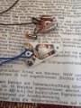
I read else ware on this site a simple pencil eraser works good, and it did. I cleaned up the contact points. Same result, both indicator lights light up. I'm beginning
To wonder since they " maybe used" if there is some sort of " insulator" missing? Little trial and error later todY to see
 
Top