High Side Switching of IGBT

crutschow

Joined Mar 14, 2008
38,578
I thought probably there's some way to also inform the timer that the micro-controller signal is low.
You could if you really need the 555 to be off when the signal is low (connect RST to the micro signal), but you would need to add a diode between V+ (anode) and the VB, to keep C4 charged when the 555 off..

Otherwise the 555 needs to keep operating so that C4 stays charged to 10V, and is available when the signal goes back high.
 

Irving

Joined Jan 30, 2016
5,191
This is good to know.

I would like to know how you were able to calculate 83mA, turn-on time, the 10uF capacitor value and how did you figure out that having 100R resistor is limiting the current to 120mA.

Please share some indepth calculation you did. I know it will take a significant amount of your time to show all this calculations, but it might just help me in my project.
There are various ways to calculate this. To answer your last question first, 120mA is simply:

I = V/R = 12v/100R = 0.12A.​

Remember the gate looks like a (non-linear) capacitor, so initially the capacitor is discharged and the gate voltage is zero so the 100R resistor defines the maximum current, which reduces as the gate voltage rises.

Another way to look at it is to use the total gate charge value from the datasheet, which is 140nC. Using the simplistic

Q = i.Δt , or, rearranging, Δt = Q/i

Knowing the DC-DC converter output is nominally 83mA gives:

Δt = Q/i = 140e-9/83e-3 =1.68e-6 ie 1.68uS.​

By putting a 10uF capacitor across the output of the DC-DC converter, it will charge to 12v, holding a charge of:

Q = CV = 10e-6 . 12 = 120uC.​

Since this represents a value ~800x the gate charge, the capacitor removes the 83mA limit (though now the 100R resistor comes into play) and allows several gate events with minor loss of voltage. As long as there is sufficient time to recharge the capacitor between gate events the turn on time will be significantly improved.

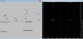
Downloading the SPICE model for the IGBT allows a better evaluation of the turn on time. The lower traces show the gate drive volt and current, and the upper traces, the collector voltage and current...

1661461401178.png

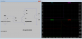
Looking closer in, we can see the turn-on time is around 200nS with a resistive load...

1661462754404.png
 

Thread Starter

MMayur

Joined Aug 25, 2022
9
There are various ways to calculate this. To answer your last question first, 120mA is simply:

I = V/R = 12v/100R = 0.12A.​

Remember the gate looks like a (non-linear) capacitor, so initially the capacitor is discharged and the gate voltage is zero so the 100R resistor defines the maximum current, which reduces as the gate voltage rises.

Another way to look at it is to use the total gate charge value from the datasheet, which is 140nC. Using the simplistic

Q = i.Δt , or, rearranging, Δt = Q/i

Knowing the DC-DC converter output is nominally 83mA gives:

Δt = Q/i = 140e-9/83e-3 =1.68e-6 ie 1.68uS.​

By putting a 10uF capacitor across the output of the DC-DC converter, it will charge to 12v, holding a charge of:

Q = CV = 10e-6 . 12 = 120uC.​

Since this represents a value ~800x the gate charge, the capacitor removes the 83mA limit (though now the 100R resistor comes into play) and allows several gate events with minor loss of voltage. As long as there is sufficient time to recharge the capacitor between gate events the turn on time will be significantly improved.

Downloading the SPICE model for the IGBT allows a better evaluation of the turn on time. The lower traces show the gate drive volt and current, and the upper traces, the collector voltage and current...

View attachment 274708

Looking closer in, we can see the turn-on time is around 200nS with a resistive load...

View attachment 274709
Thank you very much. It makes sense.

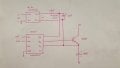
If I add a 10uF capacitor between the output of the DC-DC converter, should I also add a resistor to limit the current to 83mA since the capacitor needs to charge (initially its a short circuit) and Imax of the converter is 83mA.

Hence a resistor of about 150R to limit the current to 80mA (12/150R), the capacitor can then charge in 1.5ms ( Tau = RC = 10uF * 150R).

I can then add the 100R resistor at the gate, if I want to limit the current from the 10uF capacitor or do away with it. The circuit then looks as follows:

Circuit.jpeg

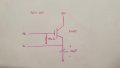
In your SPICE simulation when we switch OFF the IGBT the gate capacitor needs to discharge. Is the following circuit a good way to discharge the capacitor, rather than the current flowing backwards to the gate driver or DC-DC converter.

Turn off.jpeg

Is this thought process correct and can I implement it then?

(Forgive me for the wrong symbol used for polarized capacitor, but the notation is correct.)
 
Last edited:

Irving

Joined Jan 30, 2016
5,191
You don't need the 150R series resistor from the DC-DC converter, its current limited itself and its short-circuit current is max 130% of nominal (ie 108mA). It can also handle up to 540uF according to datasheet so 10uF isn't going to worry it.

You should have a series resistor to the IGBT. The actual value depends on the amount of gate ringing you get. The IGBT datasheet suggests Rg = 3.3Ω, but its often best to observe on a 'scope and choose accordingly. 10 - 50Ω is not uncommon.

If you're using the IR2101 driver you don't need the 10k resistor as the HO output is an active pull-down to Vs.
 
Top