 Facebook
 Google
 GitHub
 Linkedin
Hello!
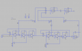
I'm looking to the state variable filter proposed from ESP in Project 153 that is a state variable filter that splits the signal in 3 bands and sums them back together.
this should give a flat response all over the spectrum when the bands are summed back together.
I simulated the circuit with LTspice and the response looks flat as expected.

R5/R6/C1/C2 cutoff frequency is set at 2200Hz
R20/R21/C5/C6 cutoff frequency is set at 170Hz
However, if i run a triangle wave of 1Khz inside of the circuit i get this

and this if the frequency of the triangle is 400Hz

In fact, at the beginning i was expecting to see the same sharp triangle at the output but It looks like each one of the 3 bands have a different phase shift and when summed together at the end they won't recreate the original shape of the triangle.
This is a visible distorsion but the text (of the related project 148) says "couldn't measure the distortion as it's below my measurement threshold, and it sat resolutely at 0.02%".
Also, the amplitude of Vout is lower then Vin but in the AC analysis graph i read that Vout has almost 0dB change from 20Hz to 20Khz.
This doesn't happen if repeat simulation with a sinewave instead of a triangle. this, though, is an analog audio circuit and there aren't be pure sine waves in audio signals that will pass through the circuit.
With the sine wave, i get only phase shifting, starting with 0° at 600 Hz.

What i see from the simulation is probably going to sound bad or at least far from similar to the original input signal.
What am i missing?
Thanks for your help
I'm looking to the state variable filter proposed from ESP in Project 153 that is a state variable filter that splits the signal in 3 bands and sums them back together.
this should give a flat response all over the spectrum when the bands are summed back together.
I simulated the circuit with LTspice and the response looks flat as expected.
R5/R6/C1/C2 cutoff frequency is set at 2200Hz
R20/R21/C5/C6 cutoff frequency is set at 170Hz
However, if i run a triangle wave of 1Khz inside of the circuit i get this
and this if the frequency of the triangle is 400Hz
In fact, at the beginning i was expecting to see the same sharp triangle at the output but It looks like each one of the 3 bands have a different phase shift and when summed together at the end they won't recreate the original shape of the triangle.
This is a visible distorsion but the text (of the related project 148) says "couldn't measure the distortion as it's below my measurement threshold, and it sat resolutely at 0.02%".
Also, the amplitude of Vout is lower then Vin but in the AC analysis graph i read that Vout has almost 0dB change from 20Hz to 20Khz.
This doesn't happen if repeat simulation with a sinewave instead of a triangle. this, though, is an analog audio circuit and there aren't be pure sine waves in audio signals that will pass through the circuit.
With the sine wave, i get only phase shifting, starting with 0° at 600 Hz.
What i see from the simulation is probably going to sound bad or at least far from similar to the original input signal.
What am i missing?
Thanks for your help
Attachments
-
 84.7 KB Views: 6


