Help understanding the PWM signal at a brushed motor

Thread Starter

abu1985

Joined Oct 18, 2015
84
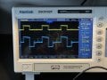
Ch2 on the scope - that's the signal on the motor leads. Ch1 is the PWM off the output of the Arduino. The PWM on the motor doesn't match the PWM out of the controller. Can someone give me some insight as to why? That ~6volts in the middle of the "off" cycle creeps up when the motor starts moving. And it stays there as the motor moves throughout the command. I'd love to fix that.

The project is just me being middle aged and tinkering around... It's nothing important.
 

Attachments

Alec_t

Joined Sep 17, 2013
15,112
During the driving pulse 'off' instants you are seeing the voltage generated by the motor acting as a dynamo.
 
Last edited:

Thread Starter

abu1985

Joined Oct 18, 2015
84
Between one motor terminal and ground? Or across the motor?If it was between one motor terminal and ground, what is happening at the other motor terminal?
It’s across the motor, not to ground. I didn’t even test to ground now that I think of it.
 

Thread Starter

abu1985

Joined Oct 18, 2015
84
Or the flyback voltage from its inductance.
Out of just curiosity, I put a diode across the motor and it didn’t help. Although at that same time my probe switched itself to x1 and I was troubleshooting seemingly high voltages that were false. Should I pop a diode back on there? I’m looking up flyback voltage as well.
 

Futurist

Joined Apr 8, 2025
725
Out of just curiosity, I put a diode across the motor and it didn’t help. Although at that same time my probe switched itself to x1 and I was troubleshooting seemingly high voltages that were false. Should I pop a diode back on there? I’m looking up flyback voltage as well.
Observe these signals at different frequencies. Is the processor itself generating variable width pulse? vary that width (duty cycle) and note how the motor voltage looks.

I don't know much about Arduino, does its board have PWM device built in?
 

Ian0

Joined Aug 7, 2020
13,112
So
It’s across the motor, not to ground. I didn’t even test to ground now that I think of it.
Does your scope have differential inputs then? Oooh - fancy 'scope!
And which of the three inputs did you use? And what did you do with the other two.

it looks like the flyback voltage due to the inductance to me. When one side of the bridge switches off current must continue to flow, so it goes through the diodes and into the motor supply in reverse.
 

Futurist

Joined Apr 8, 2025
725
I see the Arduino relies on timers to gen PWM, Timer 1 seems run at 976Hz, which is the frequency I see on your scope. The code seems to rely on a function named "analogWrite" yet has nothing to do analog, but I digress. So I don't know how you can vary the frequency, varying stuff like this often sheds light on questions like yours.

You can code Timer1 directly yourself (not using analogWrite) and choose any desired frequency, not that fixed 976Hz, I'd be interested how the motor voltage behaves as you vary frequency and duty cycle. I found this, but the frequency seems too high for PWM but I don't actually know.

C:
// 20 kHz PWM on pin 9 using Timer1
void setup() {
  pinMode(9, OUTPUT);

  // Fast PWM, TOP = ICR1
  TCCR1A = _BV(COM1A1);
  TCCR1B = _BV(WGM13) | _BV(WGM12) | _BV(CS10);
  TCCR1A |= _BV(WGM11);

  ICR1 = 800;        // sets frequency: 16MHz / 800 = 20 kHz
  OCR1A = 400;       // 50% duty cycle
}

void loop() {}
 
Last edited:

Futurist

Joined Apr 8, 2025
725
I think @Alec_t is correct from what I'm reading. Put a 50 ohm resistor across the motor something like a 10W resistor should do it. This should "dampen" that 6v part of the pulse.

Some PWM hardware apparently short the motor during the off part of a cycle.

The L298N already contains diodes to protect itself.

Also you can ignore it altogether, it does no harm.
 
Last edited:

Thread Starter

abu1985

Joined Oct 18, 2015
84
So

Does your scope have differential inputs then? Oooh - fancy 'scope!
And which of the three inputs did you use? And what did you do with the other two.

it looks like the flyback voltage due to the inductance to me. When one side of the bridge switches off current must continue to flow, so it goes through the diodes and into the motor supply in reverse.
It’s definitely not a fancy scope to my understanding. It was the cheapest I could find that seemed respectable for a novice.

i’m not sure about it having differential inputs. I’ll have to research that.
 

Thread Starter

abu1985

Joined Oct 18, 2015
84
I see the Arduino relies on timers to gen PWM, Timer 1 seems run at 976Hz, which is the frequency I see on your scope. The code seems to rely on a function named "analogWrite" yet has nothing to do analog, but I digress. So I don't know how you can vary the frequency, varying stuff like this often sheds light on questions like yours.

You can code Timer1 directly yourself (not using analogWrite) and choose any desired frequency, not that fixed 976Hz, I'd be interested how the motor voltage behaves as you vary frequency and duty cycle. I found this, but the frequency seems too high for PWM but I don't actually know.

C:
// 20 kHz PWM on pin 9 using Timer1
void setup() {
  pinMode(9, OUTPUT);

  // Fast PWM, TOP = ICR1
  TCCR1A = _BV(COM1A1);
  TCCR1B = _BV(WGM13) | _BV(WGM12) | _BV(CS10);
  TCCR1A |= _BV(WGM11);

  ICR1 = 800;        // sets frequency: 16MHz / 800 = 20 kHz
  OCR1A = 400;       // 50% duty cycle
}

void loop() {}
Using a classic 555 timer, the motor gets a nice square signal. These little motor drivers are cheap on amazon. But the 555 uses a pot to adjust the duty cycle. I’d like to figure out how to replace the 10k pot with an analog signal - say 0-5v (I would prefer 0-10v).

Also, I need a way to flip polarity for opposite direction. That’s another hurdle.
 

Futurist

Joined Apr 8, 2025
725
Using a classic 555 timer, the motor gets a nice square signal. These little motor drivers are cheap on amazon. But the 555 uses a pot to adjust the duty cycle. I’d like to figure out how to replace the 10k pot with an analog signal - say 0-5v (I would prefer 0-10v).

Also, I need a way to flip polarity for opposite direction. That’s another hurdle.
The L298N was designed to support bidirectional motor control, take a look at its datasheet. Oh and I just noticed, setting IN1 and IN2 high, will indeed short the motor, totally eliminate that 6v step but you need to have pwm drive IN1 or IN2, a circuit and software change.
 
Last edited:

MisterBill2

Joined Jan 23, 2018
27,312
Has the ts EVEN LOOKED AT THE DRIVE WAVEFORM OUT OF THE ARDUINO?? or looked at the waveform out of the driver witout a motor or anything connected?? A fully differential drive scheme requires full pull-up and pull-down capability on both lines of the driver. Anything else will not work correctly. If that has already been stated, I may have missed it.
 

Ian0

Joined Aug 7, 2020
13,112
As the L298 is a stepper motor driver, it will be equipped with inputs that produce fast decay (of the motor current) or slow decay.
Fast decay involves connecting the supply to the motor in the opposite direction, slow decay is achieved by shorting the motor out. The waveform posted by the TS is fast decay.
 
Top