Help understanding the PWM signal at a brushed motor

Ian0

Joined Aug 7, 2020
13,230
True, but the popular cheap board that is out there with the L298 does not have the stepper motor current monitor resistors, in order to use it with the common L297
Doesn't matter with DC brushed motor
The TS doesn't say which input he used. The point I'm making is that he could have achieved fast decay (which is what is observed on the scope) by his choice of input.
 

MisterBill2

Joined Jan 23, 2018
28,077
The original stepper motor driver packages had open collector outputs. I built machines using quite a few of them using the Superior Electric driver package.
 

MisterBill2

Joined Jan 23, 2018
28,077
Looking at the circuit shown in post #1, and then looking at the wave forms, two more questions stand out: First, what sort of performance is the TS expecting from the motor, and second, why drive a motor with that sort of constantly reversing power?? An "H Bridge" is fine for driving a stepper where the polarity gets reversed many times per revolution.
For a brush-type DC motor, one side gets pulled low and then the other side gets the PWM changing from OFF to ON.
 

Ian0

Joined Aug 7, 2020
13,230
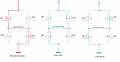
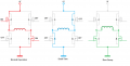
So what we are most likely seeing, is "Normal operation" followed by "dead time". Normal operation where the motor voltage is positive (assuming positive probe to the left), then "dead time" where no transistor is on, and the current goes through both bottom left and top right flyback diodes giving a voltage across the motor of the same magnitude but opposite polarity as "normal operation" lasting until the current through the motor reduces to zero.
If the TS wants to eliminate the negative pulse (can't think why) then he need to switch both top transistors or both bottom transistors on immediately after the pulse. (Switching ONE transistor on will work, as the current will go through the other diode.)
 

Thread Starter

abu1985

Joined Oct 18, 2015
84
Yes, but the TS never said which of those pins the signal was connected to!
I'm lost on the direction of the conversation here... But the PWM output of the Arduino connects to the EnA of the L298N. The L298N has discrete inputs for direction of the motor, labeled as IN1 and IN2. The direction of the motor doesn't matter, the ~6 volts is still there.

Ch1 of the scope [yellow] is right off the controller. The output pin to GND.
Ch2 of the scope [blue] is across the motor leads.

I am just trying to get the 12 volt wave across the motor to match the 5 volt wave input to the IC. With doing that, I might learn what that 6 volts is during the "off" phase, that is shown on the scope on Ch2.

Scaling the RPM of the motor is very poor. Meaning, a duty cycle of 90% is about the same RPM as 40%. I'm not getting a true square pulse to the motor it seems.
 

Ian0

Joined Aug 7, 2020
13,230
Connected to the enable pin means that it will go into the "deadtime" phase.
Try it with enable permanently enabled and drive the PWM into one of the IN inputs. That will make the current fall at half the rate.
It looks as though it is in discontinuous current mode, so the current has time to return to zero before the next PWM pulse, In that case, the average voltage does not equal supply voltage x duty cycle.
You either need more inductance or a higher frequency pwm.
 

Futurist

Joined Apr 8, 2025
941
I'm lost on the direction of the conversation here... But the PWM output of the Arduino connects to the EnA of the L298N. The L298N has discrete inputs for direction of the motor, labeled as IN1 and IN2. The direction of the motor doesn't matter, the ~6 volts is still there.

Ch1 of the scope [yellow] is right off the controller. The output pin to GND.
Ch2 of the scope [blue] is across the motor leads.

I am just trying to get the 12 volt wave across the motor to match the 5 volt wave input to the IC. With doing that, I might learn what that 6 volts is during the "off" phase, that is shown on the scope on Ch2.

Scaling the RPM of the motor is very poor. Meaning, a duty cycle of 90% is about the same RPM as 40%. I'm not getting a true square pulse to the motor it seems.
Look at the device's datasheet (middle of page 8), it says when IN1 and IN2 are both floating the motor coasts (and gens a voltage) but when IN1 and IN2 are both low (or both high), it short circuits the motor (killing any generator behavior). So its down to the software that manages IN1 and IN2.

Have you studied the datasheet? it' important!

https://www.st.com/resource/en/datasheet/l298.pdf

The brake function (Fast motor stop) requires that the Absolute Maximum Rating of 2 A must never be exceeded.
There it is, this tells you that there exists a brake capability...
 
Last edited:

MisterBill2

Joined Jan 23, 2018
28,077
When I look at the internal circuit of the IC,, shown on the data sheet, versus the circuit shown on the screenshot of post#1,
I see that the lower ends of the H-bridge (pins #1 and #15) do not seem to be connected. That tells me that no portion of any operation will be what is intended to be. Any connection to the non-powered side of the motor will be thru the base-emitter path to the driver portion.
My conclusion is that incomplete connection will cause unexplained operation.
 

Thread Starter

abu1985

Joined Oct 18, 2015
84
Connected to the enable pin means that it will go into the "deadtime" phase.
Try it with enable permanently enabled and drive the PWM into one of the IN inputs. That will make the current fall at half the rate.
It looks as though it is in discontinuous current mode, so the current has time to return to zero before the next PWM pulse, In that case, the average voltage does not equal supply voltage x duty cycle.
You either need more inductance or a higher frequency pwm.
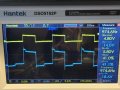
This fixed it. I put the PWM signal on the IN1 and left the ENA high. The motor had a much smoother operation. See the attached image of the scope.
 

Attachments

Thread Starter

abu1985

Joined Oct 18, 2015
84
Have you studied the datasheet? it' important!
I haven’t. I took for granted the diagrams shown around online. But putting the PWM on IN1, leaving ENA high, and IN2 low, it performs well. So I can program the PWM to pulse IN1 and IN2 for direction control.
 

Ian0

Joined Aug 7, 2020
13,230
This fixed it. I put the PWM signal on the IN1 and left the ENA high. The motor had a much smoother operation. See the attached image of the scope.
Do you see the small step in the waveform halfway through the negative part of the cycle? You next pwm pulse should start there, or earlier. It suggests that you pwm frequency should be about 2kHz minimum.
 

Thread Starter

abu1985

Joined Oct 18, 2015
84
Do you see the small step in the waveform halfway through the negative part of the cycle? You next pwm pulse should start there, or earlier. It suggests that you pwm frequency should be about 2kHz minimum.
Yep I understand. That’s interesting. Thanks for the help.
 

MisterBill2

Joined Jan 23, 2018
28,077
I haven’t. I took for granted the diagrams shown around online. But putting the PWM on IN1, leaving ENA high, and IN2 low, it performs well. So I can program the PWM to pulse IN1 and IN2 for direction control.
If that change made the circuit work, then what is obvious to me is that the circuit shown in post #1 is incomplete.. It does not seem like the motor should run if the return circuit is not completed.
 

Ian0

Joined Aug 7, 2020
13,230
If that change made the circuit work, then what is obvious to me is that the circuit shown in post #1 is incomplete.. It does not seem like the motor should run if the return circuit is not completed.
IN1=high turns on the upper output device at the left side. IN2=low turns on the lower output device at the right side.
 

MisterBill2

Joined Jan 23, 2018
28,077
Ifthe low side emitter is not connected to the motor power return, at least not according to the data sheet. Pin #8 is shown as a "ground" while the motor current is shown using pins #1 and #15. Further on, in the applications segment, the connections are confusing.
 
Top