Heat causing automotive LCD display to dim. Can't find a solution.

Poyntat

Joined May 24, 2022
60
If removing the sot23 device heavily affects the contrast then it would seem reasonable to assume that the device could be in series with the contrast control input to the lcd. You also state that the display flickers when the sot23 device is removed. Could this be due to the contrast control pin floating with the sot23 device removed which is causing the voltage at that pin to vary and the contrast to vary?
The most common scheme for adjusting the contrast of lcd displays is a simple potentiometer connected between Vcc and 0v with the wiper supplying the contrast bias voltage, usually labelled VO.
Lcds with wide temperature specs often require a more sophisticated method of contrast control to guarantee legibility over their operating temperature range. This normally means including traditional temperature sensing devices such as thermistors with an amplification stage to adjust the contrast voltage to keep the display legible as the lcd contrast parameters change with temperature.
If this issue has been happening with all of these modules then it would seem that the design of the contrast control scheme is suspect. Has there been a change in the type of lcd fitted?
Was this contrast control appropriate for another, maybe earlier, series of lcds?
 

wraujr

Joined Jun 28, 2022
260
Don't rule out relocation so quickly.
If this is a voltage regulator/reference it has been designed with compensation to operate of its specified temperature range.
But, it has been placed next to LEDs that generate heat (all LEDs generate heat) and then combine this that when the LCD is wrapped around and attached to the board the A7 has maybe been encased along with the LEDs basically creating a heat chamber.
Now all that is not necessarily a problem, but what has happened is you have raised the "typical" operating temp towards the upper limit. So, now when when you add heat you could be moving the op temp above the "designed/compensated" operating change resulting in lowered output. Its not discrete as in pass/fail. As you increase the op temp and go outside range the device will slowly go out of spec.
Don't get confused by the way you are adding heat, you are adding large amounts very quickly compared to typical environmental changes.
By relocating to opposite side, you are moving away from heat emitting LEDs, away from enclosed area, and into a more open area with free air flow that will track the ambient cabin temperature.
That said, it is interesting that with all the space on the front side why they would place it on the rear, unless their intent was they wanted close proximity to LCD for tracking/compensation that Poyntat has been talking about. Placement of part decisions are not always aribitrary. And as I mentioned two of the three pins are immediately connect to vias that take the signas to the front side.. so why place on back side when at least 2 of your 3 signals are on front side.
That said, it's not even clear that the 3rd pin is used, in which case A7 is most likely the dual Schottky diode and they are using one of the diodes as a simple voltage reference that will vary with temp (see Poyntat discussion).
 

Thread Starter

RickB93

Joined May 10, 2023
13
Hi all,

I have progress update.

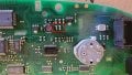
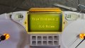
So I have managed to solve the fading issue and the A7 diode is the cause. What I've found is that if I remove the A7 chip from the board, the LCD display will continue to work but with poor contrast where the background is too bright. In the 1st pic attached, highlighted in red are two resistors which control the contrast of the display. The one on the left is 11k and the one on the right is 20k. I replaced the 11k rated resistor for 12k, and now the display's contrast is perfectly good. See 2nd pic attached of the display contrast.

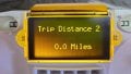
Now if I apply heat to the whole circuit board, the text on the LCD display no longer fades away. The text remains perfectly clear to read. The only issue now is when the LCD display gets hot, the contrast of the background of the display is affected, starting from the bottom. See 3rd pic attached. However, In everyday use I think this may not be an issue as the LCD display generally won't get hot enough to see this problem appear. I done a road test with the dash heaters set to full heat at full blower speed, and it took over 30 minutes of driving before the contrast issue appeared. And at this point the vehicle's interior was extremely hot. The only thing I am not able to test currently is how it performs in hot weather (not warm enough here in the UK yet and will be a couple months before we get our 5 days of summer!).

So for now, this is how far I've been able to progress in terms of finding a solution. Ideally, I think the best solution would be if the A7 diode can be replaced with one that will perform better at hotter temperatures, but with my very little technical knowledge in this area I have no idea where I'd even start to try and work out what the best replacement chip would be.

I've fed these findings back to the manufacturer of the display, so will see if they can offer a better solution. But for now, the display is function far better than before with the A7 diode removed and the resistor changed from 11k to 12k.
 

Attachments

Thread Starter

RickB93

Joined May 10, 2023
13
Don't rule out relocation so quickly.
If this is a voltage regulator/reference it has been designed with compensation to operate of its specified temperature range.
But, it has been placed next to LEDs that generate heat (all LEDs generate heat) and then combine this that when the LCD is wrapped around and attached to the board the A7 has maybe been encased along with the LEDs basically creating a heat chamber.
Now all that is not necessarily a problem, but what has happened is you have raised the "typical" operating temp towards the upper limit. So, now when when you add heat you could be moving the op temp above the "designed/compensated" operating change resulting in lowered output. Its not discrete as in pass/fail. As you increase the op temp and go outside range the device will slowly go out of spec.
Don't get confused by the way you are adding heat, you are adding large amounts very quickly compared to typical environmental changes.
By relocating to opposite side, you are moving away from heat emitting LEDs, away from enclosed area, and into a more open area with free air flow that will track the ambient cabin temperature.
That said, it is interesting that with all the space on the front side why they would place it on the rear, unless their intent was they wanted close proximity to LCD for tracking/compensation that Poyntat has been talking about. Placement of part decisions are not always aribitrary. And as I mentioned two of the three pins are immediately connect to vias that take the signas to the front side.. so why place on back side when at least 2 of your 3 signals are on front side.
That said, it's not even clear that the 3rd pin is used, in which case A7 is most likely the dual Schottky diode and they are using one of the diodes as a simple voltage reference that will vary with temp (see Poyntat discussion).
I understand your suggestion, but I think you've missed where I've said that in the summer months when it's hot (over 25oc), you'll find that when you switch on the display for the very first time the hot weather has already caused the text on the display to fade (due to how hot the interior of the car already is). So even when the display is not being used and therefore no additional heat being added by the LEDs, the problem already occurs on hot days. Therefore, relocating the A7 would not resolve this problem unfortunately.
 

Jon Chandler

Joined Jun 12, 2008
1,628
A7 may or may not be a dual diode. Several different device types have an A7 top mark as I posted.

Glad you've found a workable solution!

Looks like THE HORSE won the race.
 

drjohsmith

Joined Dec 13, 2021
1,623
Hi all,

I have progress update.

So I have managed to solve the fading issue and the A7 diode is the cause. What I've found is that if I remove the A7 chip from the board, the LCD display will continue to work but with poor contrast where the background is too bright. In the 1st pic attached, highlighted in red are two resistors which control the contrast of the display. The one on the left is 11k and the one on the right is 20k. I replaced the 11k rated resistor for 12k, and now the display's contrast is perfectly good. See 2nd pic attached of the display contrast.

Now if I apply heat to the whole circuit board, the text on the LCD display no longer fades away. The text remains perfectly clear to read. The only issue now is when the LCD display gets hot, the contrast of the background of the display is affected, starting from the bottom. See 3rd pic attached. However, In everyday use I think this may not be an issue as the LCD display generally won't get hot enough to see this problem appear. I done a road test with the dash heaters set to full heat at full blower speed, and it took over 30 minutes of driving before the contrast issue appeared. And at this point the vehicle's interior was extremely hot. The only thing I am not able to test currently is how it performs in hot weather (not warm enough here in the UK yet and will be a couple months before we get our 5 days of summer!).

So for now, this is how far I've been able to progress in terms of finding a solution. Ideally, I think the best solution would be if the A7 diode can be replaced with one that will perform better at hotter temperatures, but with my very little technical knowledge in this area I have no idea where I'd even start to try and work out what the best replacement chip would be.

I've fed these findings back to the manufacturer of the display, so will see if they can offer a better solution. But for now, the display is function far better than before with the A7 diode removed and the resistor changed from 11k to 12k.
wonder what A7 does ?
the manufacturer would not put it there for no reason, these car people cut every penny they can
I had to change resistor tolerances to save 2 pence on a car board once...
 

Poyntat

Joined May 24, 2022
60
So it seems that the contrast voltage is set to a nominal value using the two resistors which you have highlighted and the sot23 device (BAV99), which you have removed, was acting on this nominal voltage either directly or as part of a more sophisticated compensation network.
As you can see, small changes in the contrast voltage have a significant affect on the legibility of the display.
If you are going to go with the ‘no compensation’ scheme I would advise you to test a number of the lcds with the new resistor value or go with a ‘select on test‘ method for each cluster which of course would be time consuming.
I assume that no low temperature tests have been carried out, or have they?
As a general rule the lcd contrast voltage needs to increase as the temperature falls and vice versa as the temperature rises.
 

ajv

Joined Oct 15, 2024
5
Hi all,

I have progress update.

So I have managed to solve the fading issue and the A7 diode is the cause. What I've found is that if I remove the A7 chip from the board, the LCD display will continue to work but with poor contrast where the background is too bright. In the 1st pic attached, highlighted in red are two resistors which control the contrast of the display. The one on the left is 11k and the one on the right is 20k. I replaced the 11k rated resistor for 12k, and now the display's contrast is perfectly good. See 2nd pic attached of the display contrast.

Now if I apply heat to the whole circuit board, the text on the LCD display no longer fades away. The text remains perfectly clear to read. The only issue now is when the LCD display gets hot, the contrast of the background of the display is affected, starting from the bottom. See 3rd pic attached. However, In everyday use I think this may not be an issue as the LCD display generally won't get hot enough to see this problem appear. I done a road test with the dash heaters set to full heat at full blower speed, and it took over 30 minutes of driving before the contrast issue appeared. And at this point the vehicle's interior was extremely hot. The only thing I am not able to test currently is how it performs in hot weather (not warm enough here in the UK yet and will be a couple months before we get our 5 days of summer!).

So for now, this is how far I've been able to progress in terms of finding a solution. Ideally, I think the best solution would be if the A7 diode can be replaced with one that will perform better at hotter temperatures, but with my very little technical knowledge in this area I have no idea where I'd even start to try and work out what the best replacement chip would be.

I've fed these findings back to the manufacturer of the display, so will see if they can offer a better solution. But for now, the display is function far better than before with the A7 diode removed and the resistor changed from 11k to 12k.
Hi, what display you are using? That one from Aliexpress? I would like to replace it to my car also. I've seen on Ali the same problem, solved by seller advice.
Thanks in advance.
 

zuba

Joined Dec 28, 2025
1
Dear All,

I am willing to try this solution on my MFD display, from a 2005 peugeot 307.
How could I identify the "A7" diode to be removed?

thanks!
 
Top