ok permission to call me a idiot. I'm surprised the manufacturer hadn't picked up on this also.
So been looking again at other chips surrounding the SRAM to ensure no other resistors etc are actually causing the problem rather than the SRAM. The yellow chips to the left of the SRAM I've tested before, and just to be sure I tested them again this morning by applying heat to them with a soldering iron and they do not affect the display what so ever.
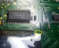
However.... what I had not noticed is that there is a very small chip on the opposite side of the board, almost directly behind the SRAM chip. See 1st and 2nd pics attached. This is what is actually causing the problem, not the SRAM chip. If I apply heat to this chip with the soldering iron the text on the display immediately goes blank.
So what has been happening during our tests is, when we heat the SRAM chip, the heat is transferring to the board and also heating this small chip located nearby on the opposite side of the board. And when we're cooling the SRAM chip and seeing the display quickly restore, it is also cooling the board and again also the chip on the opposite side of the board. So it made it appear that the SRAM chip is causing the problem when in fact it's this small chip on the opposite side.
If I remove the chip completely the contrast of the display is badly affected. See 3rd pic attached (ignore the vertical black lines, this is the problem the old original displays have due to delamination of the ribbon cable joint which I mentioned earlier in my previous post - this is why I've had the new displays made).
As a test, what I've done is removed the chip from the board, and then installed 3 wires from the board to the chip so that the board can be heat tested with the chip away from it. Now if I apply heat to the SRAM chip, it has no affect what so ever to the display (I tested by applying heat to the SRAM chip for 4 minutes with the soldering iron with no problems). If I apply heat to this chip with the soldering iron it immediately causes the text to fade and disappear from the display.
See my video here:
I cannot believe I didn't spot this small chip and test it earlier!
It looks like this chip is a switching diode? The marking on it is A7. So now my question is, what can be done to prevent this chip from causing my problem?
Ok which leds does it fade out, or it might be feeding the backpane voltage, it might be a transistor see if you can test it with a multimeter to work out if it's a npn or pnp or fet.
I've just checked several other of these instrument cluster boards I have here and they have slightly different codes for this chip. Some are A7, some are A7S and some are A7W.
If the display "fades out" , then I was thinking how could a sram cause this .
if it was heat of the sram, then then digital data out of the sram would have to change to cause this effect,
digital data does not tend to be "fade" its either there or not. and tends to be on pixel basis not per display
also it does not "return" when heat is removed.
But, LCD's do have an analog signal, a bias control voltage,
if that varies, the display will fade in / out
also , the bias voltage needed is temperature dependent,
and the bias circuit is designed to take this into account,
it sounds like the bias circuit is either not stable, or does not take into account temperature.
For a test, you could try to replace the bias voltage controller a variable resistor,
you could also measure the bias voltage with a scope, see how it changes.
A circuit schematic would be real usefull here.
BTW: Dont go sticking soldering iron on parts.
its temperature s way above the what most parts can cope with, which is why there is a soldering temperature profile,
your liable to kill the parts, or even drop small flakes of old solder on to the board,
it takes very little solder to short pins together,
"If the display "fades out" , then I was thinking how could a sram cause this .
if it was heat of the sram, then then digital data out of the sram would have to change to cause this effect,
digital data does not tend to be "fade" its either there or not. and tends to be on pixel basis not per display
also it does not "return" when heat is removed. "
Here's how, if the SRAM is a display buffer contains 8-bit pixel intensity values and say an output driver does bad, then one bit goes stuck at zero. All values are reduced by the bits value (i.e. 1,2,4,8,16,32,64.128) resulting in an overall reduction in intensity.
Only "screwy" if you don't know what you're doing or what's possible.
"If the display "fades out" , then I was thinking how could a sram cause this .
if it was heat of the sram, then then digital data out of the sram would have to change to cause this effect,
digital data does not tend to be "fade" its either there or not. and tends to be on pixel basis not per display
also it does not "return" when heat is removed. "
Here's how, if the SRAM is a display buffer contains 8-bit pixel intensity values and say an output driver does bad, then one bit goes stuck at zero. All values are reduced by the bits value (i.e. 1,2,4,8,16,32,64.128) resulting in an overall reduction in intensity.
Only "screwy" if you don't know what you're doing or what's possible.
Yes I agree .
But , to make display fade , bits would have to go away in sequence of magnitude , and
If it's brightness value ,then the stamp would be loosing data and not returning when cooled.
Not impossible , but very very unlikely.
Occams razer i find in debugging is useful.
Fading in and out and reversible, tends to indicate an analog process , and the LCD will have an analog bias circuit , which if it changes will cause just this effect. It can be mimicked by varying the bias voltage on LCDs that have a controllable bias.
So occam is pointing the bias controller as the item to look at first .
Could be wrong ,but bias is the most likely place to start that agrees with the tests done.
The TS is really trying, but sticking a 650 degree soldering iron on on SOT-23 is probably raising the die temp too fast and too high to the point device fails/shutdowns/temp stop working no matter what.
Now that he believes he has the part isolated, he needs to try the very gentle approach of SLOWLY raising the part's temp and ideally measuring package temp and verify point where failure starts.
Remember has original statement that display dimmed with just the heater turned on and putting heat behind the dash.
An 8-bit pixel is a magnitude/brightness value.
Since this is not a gray-scale/picture but text all pixels of a character have the same value.
And if one driver fails due to heat, then the other drivers may fail at a similar temp .
As each bit failures to '0' the overall intensity of each character drops by the same magnitude.
"Fading in and out and reversible, tends to indicate an analog process"
All digital logic is analog.
At the risk of being ridiculed again, I must ask another stupid question.
Would not an LCD of this era be strictly a monochrome device? And each bit of the image array turning a pixel on or off? BIT, not BYTE? In which case, corrupt data in SRAM could only result in missing or extra pixels?
I hope the TS has found his weak point and if it is the A7 device that is heat sensitive, next step it to mitigate.
Remember, the TS stated this problem has always existed in all units.
My first guess is heating from the backlight LEDS has raised the thermal operating point near its upper limit, then the
addition of heat from heater puts it over the edge.
If this is the case then relocation is in order.
Notice that at least two of the three pins are connected to vias accessible from the other side, so he may be able to remove and
mount on opposite side.
At the risk of being ridiculed again, I must ask another stupid question.
Would not an LCD of this era be strictly a monochrome device? And each bit of the image array turning a pixel on or off? BIT, not BYTE? In which case, corrupt data in SRAM could only result in missing or extra pixels?
Yes, that would be a 1-bit pixel and is a possible solution.
In 1998 we had color LCD TVs so monochrome (grayscale) LCDs would exist.
With lack of original design engineer, schematics, theory of operation, software code in microprocessor, one must "infer" what has been designed based on one's experience.
If you notice, the 8-data bit bus is also connected to the LCD display.
In my original post you'll see that the size of device is in the approximate range of pixels as calculated from looking at the screen.
Next, as a cockpit display it may want to present "monochrome" (gray scale) graphics as oppose to simple on/off pixels.
And, we really don't have a lot of extensive pictures of what the display can do, such we are left inferring.
Now if the TS was really capable, we could hook up logic analyzer to the SRAM and in no time we would be able to confirm this theory of operation.
So I say the PCB traces (8-bits) and SRAM that is read/written by uProc and can be transferred to LCD all "infers" an 8-bit monochrome (being or made in the shades of a single color, 256 levels of gray).
All extremely plausible and doable by someone who has seen this type of design.
Am I correct or is your 1-bit answer correct? We will never know.
The key is don't put down someone else's theory or hypothesis by calling it "screwy" just because you don't understand or believe it. Their experience is different than yours.
For example, in my last post I showed the location of the now questioned A7 device. An experienced engineer/tech using combo of heating and cooling, would not have typically affected A7 as its not that close and its on backside. So while I am still not convinced A7 is the problem (as opposed to just overheated during test and stopped operating) I'm hoping TS has success (and even offered a mitigation solution).
What a brilliant thread.
just like a ‘who done it‘ with the last page missing.
Looks like the BAV99 is connected to the contrast control for the lcd.
Typically the contrast control is set at a particular voltage level to give the best contrast and may be fixed or in some instances may have a temperature compensation scheme to ensure that the display remains legible as the temperature varies.
Whichever scheme is used it is important that this bias voltage remains within fairly tight limits and for the temperature compensation to work properly the sensing device must see the same temperature as the lcd.
If for instance the Vf (forward voltage) of the two diodes of the BAV99 are in some way being used to control the contrast voltage of the lcd then heating the BAV99 and not the lcd will cause a change in the contrast control voltage and a corresponding change in lcd contrast. In your case the contrast is drastically lowered.
Another possibility is that the BAV99 is being used in its more traditional role as a protection device on the lcd contrast control and that the increase in leakage current caused by heating it is changing the lcd contrast voltage and causing the issue.
If it is a protection device then it can be removed without affecting the lcd for test purposes.
What a brilliant thread.
just like a ‘who done it‘ with the last page missing.
Looks like the BAV99 is connected to the contrast control for the lcd.
Typically the contrast control is set at a particular voltage level to give the best contrast and may be fixed or in some instances may have a temperature compensation scheme to ensure that the display remains legible as the temperature varies.
Whichever scheme is used it is important that this bias voltage remains within fairly tight limits and for the temperature compensation to work properly the sensing device must see the same temperature as the lcd.
If for instance the Vf (forward voltage) of the two diodes of the BAV99 are in some way being used to control the contrast voltage of the lcd then heating the BAV99 and not the lcd will cause a change in the contrast control voltage and a corresponding change in lcd contrast. In your case the contrast is drastically lowered.
Another possibility is that the BAV99 is being used in its more traditional role as a protection device on the lcd contrast control and that the increase in leakage current caused by heating it is changing the lcd contrast voltage and causing the issue.
If it is a protection device then it can be removed without affecting the lcd for test purposes.
The table I linked in post #41 lists many possibilities for an A7 top mark: dual diodes, linear voltage regulators, P-channel mosfets, NPN transistors to name a few.
I am pretty sure I have some A7-marked components in .my collection, but I can't remember which part it is.
A dual-diode seems to make the least sense in this case. If you can trace the connections, that may provide some clues. Connections to power rails, capacitors in parallel or resistors in series or parallel will provide some ideas what the part is.
Thanks for all the replies. I'm currently away this weekend so will have a proper read over these next week. Thanks for all the input.
I done another test this morning with heat. So I've identified it is definitely 100% this A7 chip which is causing my problems with the text disappearing from the display when the instrument cluster gets hot. What I've done to confirm this is remove the A7 chip from the board, and connect it via 3 wires between the board and the chip, that way I can place the A7 chip away from the board when testing with heat (as mentioned in my previous post). So now, when I apply heat all over the instrument cluster's board (with the A7 chip placed away from the board so it remains cool) the display continues to work absolutely fine regardless of how much heat I apply to the board. I tested a good 5 minutes with the hair dryer at full heat and the display worked absolutely fine throughout (normally with the A7 chip fitted on the board the text on the display would fade away and disappear completely within 10 seconds of doing this test).
Now if I apply heat to the A7 chip only (again whilst the chip is away from the board connected via 3 wires), the text on the display quickly disappears if I apply 100oc or more to it with a soldering iron (I have a soldering workstation that allows me to set the temperature between 100oc and 500oc. As soon as I remove the soldering iron from the A7 chip the display very quickly restores to working as it should.
So it is definitely the A7 chip which is causing my problem for sure.
Just to clarify some points:
- this is a problem which has been there with these instrument clusters from day 1 since the vehicles were new. So I don't think replacing the chip with a new like for like item would make any difference.
- the problem occurs either on hot days (where the temperature is above 25oc) or if you run the dash heater vents for long period of time which builds up heat behind the instrument cluster, thus heating up the board. So relocating the chip to somewhere else on the board will not make any difference. On very hot days, due to the build up of heat in the interior of the car, the screen will already be affected when you first turn it on.
So I think the only solution would be:
1. if a better alternative chip can be fitted
or 2. if this chip can be bypassed and the resistors which control the contrast of the display be altered to allow the LCD to display correctly.
The table I linked in post #41 lists many possibilities for an A7 top mark: dual diodes, linear voltage regulators, P-channel mosfets, NPN transistors to name a few.
I am pretty sure I have some A7-marked components in .my collection, but I can't remember which part it is.
A dual-diode seems to make the least sense in this case. If you can trace the connections, that may provide some clues. Connections to power rails, capacitors in parallel or resistors in series or parallel will provide some ideas what the part is.
Hi @Jon Chandler
was trying to highlight your valubale comment to @Poyntat , as they seem late to the chat and might have missed it
we think its a bav99, but might not be,
Thanks for all the replies. I'm currently away this weekend so will have a proper read over these next week. Thanks for all the input.
I done another test this morning with heat. So I've identified it is definitely 100% this A7 chip which is causing my problems with the text disappearing from the display when the instrument cluster gets hot. What I've done to confirm this is remove the A7 chip from the board, and connect it via 3 wires between the board and the chip, that way I can place the A7 chip away from the board when testing with heat (as mentioned in my previous post). So now, when I apply heat all over the instrument cluster's board (with the A7 chip placed away from the board so it remains cool) the display continues to work absolutely fine regardless of how much heat I apply to the board. I tested a good 5 minutes with the hair dryer at full heat and the display worked absolutely fine throughout (normally with the A7 chip fitted on the board the text on the display would fade away and disappear completely within 10 seconds of doing this test).
Now if I apply heat to the A7 chip only (again whilst the chip is away from the board connected via 3 wires), the text on the display quickly disappears if I apply 100oc or more to it with a soldering iron (I have a soldering workstation that allows me to set the temperature between 100oc and 500oc. As soon as I remove the soldering iron from the A7 chip the display very quickly restores to working as it should.
So it is definitely the A7 chip which is causing my problem for sure.
Just to clarify some points:
- this is a problem which has been there with these instrument clusters from day 1 sinc
What a brilliant thread.
just like a ‘who done it‘ with the last page missing.
Looks like the BAV99 is connected to the contrast control for the lcd.
Typically the contrast control is set at a particular voltage level to give the best contrast and may be fixed or in some instances may have a temperature compensation scheme to ensure that the display remains legible as the temperature varies.
Whichever scheme is used it is important that this bias voltage remains within fairly tight limits and for the temperature compensation to work properly the sensing device must see the same temperature as the lcd.
If for instance the Vf (forward voltage) of the two diodes of the BAV99 are in some way being used to control the contrast voltage of the lcd then heating the BAV99 and not the lcd will cause a change in the contrast control voltage and a corresponding change in lcd contrast. In your case the contrast is drastically lowered.
Another possibility is that the BAV99 is being used in its more traditional role as a protection device on the lcd contrast control and that the increase in leakage current caused by heating it is changing the lcd contrast voltage and causing the issue.
If it is a protection device then it can be removed without affecting the lcd for test purposes.
I believe you are correct in that this A7 chip is connected to the contrast control for the LCD. If I remove the chip, the contrast of the display is heavily affected and the display flickers slightly.
The MG rover still has a great following,
seems unusual one is not around "on the web", which one is it
ttps://www.mg-rover.org/threads/wiring-diagram.417710/

 Facebook
 Google
 GitHub
 Linkedin