Heat causing automotive LCD display to dim. Can't find a solution.

bassbindevil

Joined Jan 23, 2014
923
I'm pretty sure that it is impossible for the data in the SRAM to affect the display contrast. That's down to the choice of LCD and bias voltage. A while back I looked into alternatives to the Sharp character LCD that was in a product, and what I remember a couple decades later was that the "extended temperature range" models all required a negative bias voltage, which was inconvenient, so we kept using the original display.

Try cooling the display using a judicious amount of freeze spray or "canned air".
 

Thread Starter

RickB93

Joined May 10, 2023
13
Thanks for all the replies.

Apologies for the confusion regarding how the heat issue has been tested. I'll clarify below as I realise I missed out how we have gone about testing this in more detail.

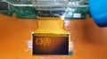
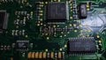
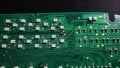
At first we assumed it was an issue with the display itself, so the display was tested by heating it in isolation up to 100oc and it continued to operate fine (with a slight change to the background contrast). The board was kept at a normal room temperate. See 1st pic attached which shows the display at normal room temperature, and the 2nd pic attached showing the display after heating to approx 60-70oc.

We then began to apply heat to the board firstly starting with a hair dryer and found that applying heat in the area where the SRAM is located affected the display, causing the display to dim.

We then tested every individual chip on the board in isolation by applying heat to individual chips using a soldering iron, and found that the SRAM chip is very sensitive to heat and will quickly cause the display to dim. See my video here I've just uploaded which shows this:

The LCD display is illuminated by a number of PLCC4 LEDs behind the display, these remain at the same brightness when the display dims. So it's not the LEDs that are dimming, but seems to be the contrast of the display which is affected when the SRAM chip is heated. The whole display goes dark to the point it is completely unreadable, but the LEDs behind the display are still operating at full brightness.

Just to answer some of the questions that have popped up in the responses
- the original SRAM chip fitted from factory is the 125oc rated version. We have tried replacing this with a brand new 125oc rated version SRAM chip, but found this made no difference and the display still continues to dim when the SRAM chip gets warm.

- we have tried cooling the SRAM chip after applying the heat with the soldering iron, and it will restore the display quicker the faster we cool the SRAM chip back to room temperature.

Hopefully this clarifies some of the confusion, apologies for that.
 

Attachments

wraujr

Joined Jun 28, 2022
260
From Post #7, So, Item (1) - What is the number on those little black 8-pin parts as the jpeg is blurry and it looks like 102
 

Thread Starter

RickB93

Joined May 10, 2023
13
OK, here's my theory. Yes, the U6264AS1A is a "Automotive 8K x 8 SRAM" designed for wide temp range.
It is obviously wired to a device just off-screen to the top, that I will call Display Controller" or DC.
Next, I notice your display is a 5-6 line, 8x10, 15 char per line or roughly 50 x 120 = 6K pixels.
Your SRAM is 8Kx8, therefore I believe this SRAM is your display buffer with each pixel being an 8-bit intensity.
From your description you are not losing memory contents as when the part cools, the display intensity returns.
But, what if you were losing a bit on your data bus (i.e. was a 1 and goes to 0), then all pixels would uniformly decrease in value and the result would be lower overall intensity...
From your picture and the SRAM data sheet, the eight (8) PCB traces coming from under the left side of device are most likely the 8-bit data bus and they route up to the DC above and the signals pass thru black, 8-pin devices.
These 8-pin devices are most likely quad serial resistors (i.e. 4 per package) that are being used for serial termination to reduce signal degradation such as ringing and possibly edge speed for EMC reasons.
Serial termination resistors are typically 22 to 33 ohms AND they should be placed close to the "driver".
So, Item (1) - What is the number on those little black 8-pin parts as the jpeg is blurry and it looks like 102 which would be 1K and this would absolutely be a problem/design flaw.
Next, Item (2) - As mentioned serial term resistors should be placed close to driver, BUT a data bus has multiple drivers, the DC drives data when writing the buffer memory and the SRAM drives the data bus when the display buffer is read by the DC.
SO, Which driver gets the series term?? Answer (and this is always debated), no one. Series termination should not be used on a bi-directional data bus (once again, always debated).
So, my theory is that when you heat the SRAM part you are "weakening" its drivers and combined with the mis-used series termination resistors and the fact that the 8 data traces have different lengths are causing one of the data bits to be received incorrectly by the DC resulting in reduced values, hence reduced intensity.
The two (2) black, 8-pin devices on the left (out of five, the other three are used properly on address lines), could be removed and replace with shorting wires (i.e. 4 wires: 1-8, 2-7, 3-6, 4-5) as a test.
Thank you for your detailed response.

Yes the 8 pin devices are marked with the number 102. And yes, you are correct that none of the memory is being lost when the dimming happens. The SRAM chip I believe stores all the trip date which is displayed on this LCD, such as trip distange, MPG, fuel range, average speed etc and none of this data is ever lost when the SRAM chip is heated and the display dims.

What would happen if I remove the two left 8pin devices and solder the connections directly as you suggest? Do you think the display will operate fine without these? I can test this on a test board I have.

Unfortunately electronics is not my background, I simply had these displays made from a automotive LCD display specialist for me, I simply just do the installation side i.e. desoldering the old displays and soldering the new ones on. So I may ask some very sill basic questions.
 

wraujr

Joined Jun 28, 2022
260
Whoa, if I am reading PCB traces, someone is using 1K resistors for serial termination and that will absolutely cause issues.
You could actually just "short" out the resistors by adding wire jumpers, one from pin 1 to 8, one from 2 to 7, etc...
That said if I have read PCB wrong we could damage circuit.
BTW if you had told me 100 (10 ohm) or 101 (100 ohm) I might say they were correct.
Step (1) Verify Part is Actually 4 Serial Resistors by using ohm meter to read pin 1-8 (should be 1Kohm) and same for 2-7, 3-6, 4-5.
:-1234-:
:-8765-:
Could be rotated 180 as I don't see pin 1 markings.
Step (2) Trace from resistor network packages (lower pins) to SRAM pins so we can verify the resistors are connected to the data pins of SRAM (i.e. D0-D7)
Step (3) Can we get photo of part I am calling the Display Controller and possible see if you can trace from resistor to DC pin number. This would help confirm that these are actually series termination and not pullup resistors. I will say PCB traces really imply serial. But the part could actually be a 7 resistor pullup in which case one of the eight pins would be connected directly to 5V (since SRAM is 5V part).
Another test would be measure voltage with meter on all 8 pins, if serial resistors and unit operating you'll get 1-4V (depends on display data), but if you get 5.0V could be pullup. Also pullup resistor networks typically use pin 8 as common/VCC.

Finally if above too much and you are adventurous and good with soldering.. You could solder 1/8 W, say 470 ohm in parallel with each 1K of the eight resistors to lower resistance. Doesn't solve but should decrease problem.
 

Thread Starter

RickB93

Joined May 10, 2023
13
Whoa, if I am reading PCB traces, someone is using 1K resistors for serial termination and that will absolutely cause issues.
You could actually just "short" out the resistors by adding wire jumpers, one from pin 1 to 8, one from 2 to 7, etc...
That said if I have read PCB wrong we could damage circuit.
BTW if you had told me 100 (10 ohm) or 101 (100 ohm) I might say they were correct.
Step (1) Verify Part is Actually 4 Serial Resistors by using ohm meter to read pin 1-8 (should be 1Kohm) and same for 2-7, 3-6, 4-5.
:-1234-:
:-8765-:
Could be rotated 180 as I don't see pin 1 markings.
Step (2) Trace from resistor network packages (lower pins) to SRAM pins so we can verify the resistors are connected to the data pins of SRAM (i.e. D0-D7)
Step (3) Can we get photo of part I am calling the Display Controller and possible see if you can trace from resistor to DC pin number. This would help confirm that these are actually series termination and not pullup resistors. I will say PCB traces really imply serial. But the part could actually be a 7 resistor pullup in which case one of the eight pins would be connected directly to 5V (since SRAM is 5V part).
Another test would be measure voltage with meter on all 8 pins, if serial resistors and unit operating you'll get 1-4V (depends on display data), but if you get 5.0V could be pullup. Also pullup resistor networks typically use pin 8 as common/VCC.

Finally if above too much and you are adventurous and good with soldering.. You could solder 1/8 W, say 470 ohm in parallel with each 1K of the eight resistors to lower resistance. Doesn't solve but should decrease problem.
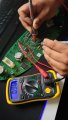
I've read the resistance and you are correct, it is near enough 1k ohms across all pins. See 1st pic attached. I got a readying of 997-998 ohms across all pins. see 1st pic attached.

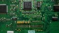
Also, see 2nd pic attached with the SRAM and also the display removed so you can see where all the connections lead to. The connections from the resistors go to pins 11-13 and 15-19 which are DQ0 to DQ7 (data in/out) according to the data sheet.

The chip you're referring to as the controller is also shown in the 2nd pic. The serial numbers on it are 4C1 HD SI 6433042F C33 VD054210488. I can't seem to find a data sheet for this using these serial numbers though.
 

Attachments

wraujr

Joined Jun 28, 2022
260
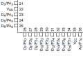
The plastic body bevel (pin 1) is on the upper left, so it looks like you are connected to D8/P30 to D15/P37 (i.e. a data bus)

1683817383316.png
 

wraujr

Joined Jun 28, 2022
260
So, yes, I would feel comfortable either:
(1) Remove the two (2) left-most resistor networks and replace with wires, essentially creating a 0 ohm resistor.
or
(2) Solder/Tack little wires in parallel creating a 0 ohm and 1K ohm in parallel that gives 0 ohm resistance and allows you to back out the modification a little easier.

You will need to do only the eight data lines, the 102 parts on the address lines are OK for now.
 

Thread Starter

RickB93

Joined May 10, 2023
13
So, yes, I would feel comfortable either:
(1) Remove the two (2) left-most resistor networks and replace with wires, essentially creating a 0 ohm resistor.
or
(2) Solder/Tack little wires in parallel creating a 0 ohm and 1K ohm in parallel that gives 0 ohm resistance and allows you to back out the modification a little easier.

You will need to do only the eight data lines, the 102 parts on the address lines are OK for now.
I have removed the two resistors and soldered the connections directly with some wire. Very tricky with the connections being so tiny but got there in the end. The screen still displays as it should, however it is still dimming when heat is applied to the SRAM chip with a soldering iron.


BTW, excellent data and pictures you are supplying.
Glad they're proving useful, trying to be as detailed as I can :)

Also, curious, are we talking BEE-MER or POOR-SHA (two syllable pronunciation intended)
You're close, the clusters are from the Rover 75/MG ZT models, but many parts and the tech is mostly BMW as the MG Rover group was owned by BMW when these models were developed.
 

Attachments

wraujr

Joined Jun 28, 2022
260
Well darn.....
One clarification needed..
You have used "dimming" (and the picture appears dimming).
But then you said " The whole display goes dark to the point it is completely unreadable, but the LEDs behind the display are still operating at full brightness." This implies all the pixels are getting "blacker".
I suspect you meant "blank".
So are all the pixels getting whiter/turning off or getting darker/turning full on?
 

Thread Starter

RickB93

Joined May 10, 2023
13
Well darn.....
One clarification needed..
You have used "dimming" (and the picture appears dimming).
But then you said " The whole display goes dark to the point it is completely unreadable, but the LEDs behind the display are still operating at full brightness." This implies all the pixels are getting "blacker".
I suspect you meant "blank".
So are all the pixels getting whiter/turning off or getting darker/turning full on?
Yes sorry the text slowly fades away to the point the screen is just blank. The background remains the same. So it's just the text that disappears.
 

wraujr

Joined Jun 28, 2022
260
OK, here's another "Hail Mary Pass" (Do you have those in your Football? Assuming you're in England since Rover)
Pin 1 of the SRAM is listed as "n.c.", however it has been connected, along with pin 26 to a pullup resistor (you can see this in picture where SRAM removed).
Sometimes chip manufacturers will use NC pins as connection points for special manufacturing tests...and
the user should really not connect any signal/voltage to that pin.
You could try, gently while soldering pin 1, lift the tip of the pin up and off the pad leaving it floating in the air...
 

wraujr

Joined Jun 28, 2022
260
OK, got another one.
Along the LCD connections you see a string of chip capacitors (yellow guys), but at the rightmost end there is a cylindrical resistor with colored strips... It goes to LCD display pin... Could be some type of bias resistor and pretty close to SRAM,
Are you sure it's not this resistor that you're heating????
 

Thread Starter

RickB93

Joined May 10, 2023
13
ok permission to call me a idiot. I'm surprised the manufacturer hadn't picked up on this also.

So been looking again at other chips surrounding the SRAM to ensure no other resistors etc are actually causing the problem rather than the SRAM. The yellow chips to the left of the SRAM I've tested before, and just to be sure I tested them again this morning by applying heat to them with a soldering iron and they do not affect the display what so ever.

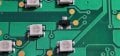
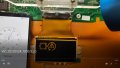
However.... what I had not noticed is that there is a very small chip on the opposite side of the board, almost directly behind the SRAM chip. See 1st and 2nd pics attached. This is what is actually causing the problem, not the SRAM chip. If I apply heat to this chip with the soldering iron the text on the display immediately goes blank.

So what has been happening during our tests is, when we heat the SRAM chip, the heat is transferring to the board and also heating this small chip located nearby on the opposite side of the board. And when we're cooling the SRAM chip and seeing the display quickly restore, it is also cooling the board and again also the chip on the opposite side of the board. So it made it appear that the SRAM chip is causing the problem when in fact it's this small chip on the opposite side.

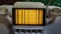
If I remove the chip completely the contrast of the display is badly affected. See 3rd pic attached (ignore the vertical black lines, this is the problem the old original displays have due to delamination of the ribbon cable joint which I mentioned earlier in my previous post - this is why I've had the new displays made).

As a test, what I've done is removed the chip from the board, and then installed 3 wires from the board to the chip so that the board can be heat tested with the chip away from it. Now if I apply heat to the SRAM chip, it has no affect what so ever to the display (I tested by applying heat to the SRAM chip for 4 minutes with the soldering iron with no problems). If I apply heat to this chip with the soldering iron it immediately causes the text to fade and disappear from the display.

See my video here:

I cannot believe I didn't spot this small chip and test it earlier!

It looks like this chip is a switching diode? The marking on it is A7. So now my question is, what can be done to prevent this chip from causing my problem?
 

Attachments

Thread Starter

RickB93

Joined May 10, 2023
13
I've just checked several other of these instrument cluster boards I have here and they have slightly different codes for this chip. Some are A7, some are A7S and some are A7W.
 
Top