If the cap is going to be used for switch debouncing(I don't know what your final circuit will be, but the one in post #97 won't provide switch debounce) it will take some time to charge up via the pull-up resistor. Make sure that doesn't adversely affect the clock pulse leading edge. The clock input should change almost immediately, not slowly. The maximum rise time when the supply voltage is 5V is specified as being only 15 microseconds.
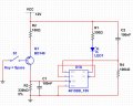
You can do something like this to increase current gain: View attachment 101410
EDIT: R1 should be 200 ohms. Or you can connect as a Darlington if the relay will tolerate the reduced voltage.
@dl324 ... did you mean a 2n3904 transistor. NOT a 2n3094? ... The 2n3904 worked.
Hi guys ... Update. I did this circuit on a breadboard and things seem ok. (See Attached) There are things I would like to work out still.
The debouncing is still there. Not sure which component value to increase/decrease to resolve the issue.
The other is default on state of the 4013. As I apply and remove power to the breadboard, in 30 sec intervals. Sometimes the LED and Relays are active when power is applied to the circuit, somethings they are not. 80% of the time, I would say the both sides of the 4013 are active, or deactive, together when power is applied to the circuit.
Maybe I'm thick, but I don't see why you need all this complication.
It seems that the simple circuit that hp1729 posted should work if all you want to do is turn a relay on and off. The "latching" is done with one SPST switch.
Maybe I'm thick, but I don't see why you need all this complication.
It seems that the simple circuit that hp1729 posted should work if all you want to do is turn a relay on and off. The "latching" is done with one SPST switch.
I need 2 separate N.O. PB to send a ground when pushed, to activate 2 separate Toggling Latching circuits. These latching circuits will directly power a 12V LED, incandescent 3 watt bulb and a 12v coil with 320-500 ohm coil resistance.
I have not tried hp1729 circuit on a breadboard, just a stimulator. To me, the 4013 looks to be simpler circuit to activate the components I listed above.
The rising edge of the clock pulse is ~30uS using your circuit. That is outside the 10uS spec, so clocking may be unreliable.
The R1C1 time constant is rather short, so may not catch all the contact bounce.
With both the Set and Clear inputs of the 4013 grounded the start-up state may be indeterminate.
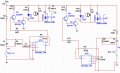
Here's what I'd try.
The clocking is modified to shorten the rise time. C2/R3 ensure the Set input now starts high at power-up to give a consistent initial state.
Alec ... seems you are saying this circuit will have to be activated by a 12v trigger ... instead of a ground trigger. Correct? ... this will offer consistent power on state and no denounce?
Mcasale ... i understand. Wish it was that simple. I have it done already .... I'm building a KNIGHT RIDER KITT car. The buttons and electronics that go in the car come with push buttons with 12v 3w bulbs in the buttons. ... the electronics offered to build the car have either negative inputs or negative pulse outputs.
That's why I need stuff to work off of a ground in and out.
@Alec_t ... Thanks for this latest. I have to get more resistors to try it on my breadboard. ... I did attempt to take your previous drawing and add a PNP to convert it to Ground pulse. It mostly worked on my breadboard. Didn't always trigger the 4013 and seemed to bounce too. See attached. ... I post my findings on your latest. Thank you so much for the help.
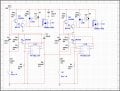
Alec_t ... I put together what I believe to be the full circuit on my SIM. Can you please review?
Also, is both C2/C5 & R6/R12 needed? Do I only need C2/R6?
On my SIM. After a few toggles of either trigger. The Output showed to be stuck in whatever the last state was. After waiting a few seconds, then retriggering. The circuit was able to change states again. Does your SIM have the same results?
Yep. My mistake! I did do the modification you mentioned, see attached.
I did try it out in my SIM. If I toggled to quickly. It didn't respond. As long as I give a few seconds in between toggling, all was good. I will be getting resistors shortly to try this out on my breadboard. I'll let you know what I find.
Thank you soooooo much Alec_t ... I can see the light at that end of the tunnel on this.
What is "too quickly"? The debounce capacitor has to stay charged long enough that switch bounces can die out, but has to be given time to charge and discharge between successive triggers. In my sim I think that was about 50mS in total.
I trust your SIM more than mine In my SIM, if I toggle the switch quickly. Pressing the spacebar consistently at 2 click per second, every second ... It did not always respond.
Alec_t ... I just tried the circuit on my breadboard. The result ... it did not latch, only pulsed when pushed.
When I pressed the button, I had an active output. Release the button, no output.
I tried multiple configurations to the circuit, swapped resistance values and found no solution. ... the only way I got it to latch was to remove C1 from 12v. And place it in parallel with R1. Then hold the button for a second. It latched.
Pressing the button just pulsed the output, had to hold the button for a latch.
Hmm. What neither my sim nor yours explicitly shows are the power connections to the IC. Do you have a decoupling cap (100nF) between pins 7 (GND) and pin 14 (V+), very close to the pins?
 Facebook
 Google
 GitHub
 Linkedin