Frequency Response Heterojunction Bipolar Transistor

Thread Starter

insyspower

Joined May 29, 2017
34
I am sure the emitter were not interchanged (reversed), because i checked many times and it was right.
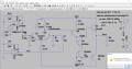
I think all the resistors on this circuit difer exactly 1% from the design values, for 10K resistor i got 9.95K (multimeter) and so on for other resistences.10K have 1% tolerance, 2.7K and 33K have 5% tolerance.

How to check if one real transistor is more acurate than the other transistor?
Where/How exacty do i connect the new resistence and where to check if the voltage is greater or less than zero?
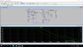
Can you implement that change on LTspice ?
 

Attachments

Last edited:

JoeJester

Joined Apr 26, 2005
4,390
If you want the simulation to show closer to what your circuit shows, change the resistors in the schematic to the values you actually read for each part.

Make sure your simulation supplies IS the same as your voltage supplies

Make sure your simulation signal generator is exactly as the "real" signal generator.

Then the only errors left are the model errors for each transistor.
 

Thread Starter

insyspower

Joined May 29, 2017
34
Another factor is the spread of transistor parameters. For example, the voltage difference of the Base-Emitter voltage can reach 50 mV.
With an amplification of 200, this should shift the output by 10 V.
On LTSPICE i think the Gain of 2N3904 is Bf=300, Bf is the Gain or maximum Gain?
What is the ideal Gain value on this 2 transistors (to use on my real circuit) ?
Which parameters i have to take in consideration when add one transistor to my circuit, i think IC, VBE, IBE, Gain are important.
And what values should these parameters ideal have?
On the datasheet only shows the maximum or minimum, but not the typical (ideal) value.

A simple solution is to select a resistor in the collector or emitter
transistor of the second stage.
You can connect in parallel to the soldered resistor one more resistor, which is much higher than the nominal value.
If the voltage is greater than zero, it is necessary to reduce the resistor in the collector (for example, to seal the parallel resistor.
If the voltage is less than zero, then the resistor is in the emitter. Another method is to use a variable (tuning) resistor.
You use an amplifier without general feedback. Feedback stabilizes the operating point.
Where/How exacty do i connect the new resistence and where to check if the voltage is greater or less than zero?

This voltages values on the real multimeter are wrong, compared to LTSpice:
Voltage on Q4 Colector = 8.3V, in SPICE= 960mV
Voltage on Q7 Base = 7.5V, in SPICE= -287mV
Voltage on Q3 Base = 7.5V, in SPICE= 960mV
Voltage on Vout = 7.5V, in SPICE= 335mV

i changed the resistences values on LTspice, to the values i got on the multimeter: for example, 10K changed to 9.95K etc.
 
Last edited:

Bordodynov

Joined May 20, 2015
3,431
When talking about amplification of an operational amplifier, we mean (usually) voltage gain. The ideal operational amplifier has a zero output voltage when the input voltage at the output is zero. In a real amplifier, the output voltage is adjusted to zero, by adjusting the internal resistors. Apply even laser tuning of resistors.
A simple way to reduce the overall, resulting denomination, is to use an additional, parallel-connected resistor.
R=R1IIR2=R1*R2/(R1+R2)
 

Thread Starter

insyspower

Joined May 29, 2017
34
Now all the voltages on LTspice match (approximately) the voltages i got with a multimeter in my real circuit.
I just changed the position of all components on the breadboard to other position.
It seems was a bad contact somewhere on the breadboard and thus i was getting wrong readings on a multimeter.
My circuit is the same as post #36. The frequency is 100KHz.
For a Vin of 20mV i get on LTspice Vout= 5.65V, which i think is right since the transistors have a gain of 300.
But on a real circuit i got Vout around 1.5V.
 

Bordodynov

Joined May 20, 2015
3,431
Is the output signal of an undistorted sine? What is the constant output voltage when there is no signal at the input? What is the supply voltage?
 
Last edited:

Thread Starter

insyspower

Joined May 29, 2017
34
Yes Vout is undistorted, it's pure sine wave.
Output voltage varies, it's very close to 0V, most of the time is around 0.34V, sometimes is 0.15V or 0.54V.
Supply voltage is +-10V.
 

Thread Starter

insyspower

Joined May 29, 2017
34
i want to calculate the Total Harmonic Distorcion (THD), of this signal (Vout_ltspice.png).
My Digital Osciloscope is Sefram 5362 DC, user manual link
https://www.hik-consulting.pl/files/sefram-oscyloskopy-5322dc.pdf

On the MATH menu i choose FFT (Fast Fourier Transform).
But when i change the scale of the sine wave from 2V to 1V (yellow), the magnitude also changes a bit for some harmonics, but the fundamental harmonic is always equal to 11dB.

For vertical scale=1V/div, and M=5ms/div, f=1KHz, i got first harmonic=-20dB, 2nd=-23dB, 3rd=-24dB, 4th=-27dB, 5th=-30dB, 6th=7th=-32dB, 8th=-37dB and 9th harmonic =-43dB, THD=4.32
For vertical scale=2V/div, and M=10ms/div, f=1KHz, i got first harmonic=-26dB, 2nd=-28dB, 3rd=-29dB, 4th=-33dB, 5th=-37dB, 6th=-40dB and 7th harmonic =-40dB, THD=1.985 (same for f=100KHz).

So the results are diferent, so what scale (V/div), should i use?
The Amplitude of Vout yellow signal is +-5V.
 

Attachments

Last edited:

Thread Starter

insyspower

Joined May 29, 2017
34
How do i Display the Fourier Transform of a Trace on LTspice iv?
On the menu command View=>FFT, the Vout i get on Ampop_Q345 is very diferent to what i get on digital osciloscope.
 

Attachments

Last edited:

Bordodynov

Joined May 20, 2015
3,431
I do not understand why you built an input circuit of resistors. In reality, any measuring device has in addition to the input resistance also the input capacitance. Add a capacitor to the simulation.
FFT analysis must be done for the steady-state process. On the chart, you must display the tail of the calculation. To do this, you must set the start time for saving the results, greater than the initial transient.
 

Thread Starter

insyspower

Joined May 29, 2017
34
Thanks, i understand now.
On Opamp.zip file i got 2 circuits the Draft.asc works fine, but on the Ampopcompleto5.asc i got an error (image OpAmp5.png).
i have no idea how to fix it.
diferential.png is the circuit i have to build on ltspice, then i got the above error.
 

Attachments

Last edited:

Thread Starter

insyspower

Joined May 29, 2017
34
Thanks.
My next step is to calculate FFT using ltspice, i now from menu view -> FFT, but i need to add this expression "V(vout)/max(V(vout))", but it's shows an error message "! Syntax error: function max requires exacty two arguments!".

Also on the file Ampopcompleto7.asc i got an Gain of about 100, Vout/Vin, since Vin is 50mV, and Vout is 5V, but i want more Gain of about 300.
I already included two resistences of 2K Ohm, to increase input signal, my osciloscope shows a distorted signal at 5mV, so i need to increase Vin, but i want the same Gain of about 300, i don't know what i have to change/include on the circuit to get near that Gain.
I still want the waves to be almost pure sinusoidal, with no saturation crops etc.
 

Attachments

Thread Starter

insyspower

Joined May 29, 2017
34
Thanks, that help a lot!
i know the Gain of that circuit is 100 (the same), but i need a higher Gain of about 300.
Someone told me that the FFT function should start at zero for lower frequencies, the type of curve is exacty like that.
 
Top