Frequency Response Heterojunction Bipolar Transistor

Thread Starter

insyspower

Joined May 29, 2017
34
Well thanks to you i advanced with my project, i have been stuck on it for some months.

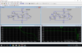
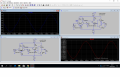
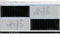
The circuit i have now is a Operacional Amplifier Equivalent Subcircuit.
I have to determine Vout, Vin, Gain.
The Vin i know i got it right, but Vout and Gain i have no ideia if it is correct.
On Ampop circuit Vout is maybe right, but with the HBT i have no ideia if its correct.
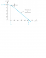
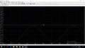
is the Vout and Gain correct for both circuits? (images Vout.png, AC_sweep.png)

Also where i can buy cheap BFP640F Transistors, i need at least 5 transistors, at maximun i buy 10 or 20.
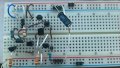
Maybe is a dumb question, but in my circuit i have some PNP transistors BJT and the BFP640F is NPN !!!, i have to build that circuit in a breadboard and Determine Vout, Vin, Gain, etc. i have to replace the BJT PNP with the BFP640F but this transistor is NPN, how i do connect them in a breadboard, the emitter is reversed !!!
 

Attachments

Bordodynov

Joined May 20, 2015
3,431
It is difficult to develop and produce the correct circuit and with transistors having a limiting frequency of 1 GHz. In fact, you can make a single-stage amplifier. If you try to use more cascades, then the probability of success is very low, i.e. You need a lot of luck and a lot of experience. The PNP transistor can be used to stabilize the mode. In this case, it can be a general-purpose transistor.
 

Thread Starter

insyspower

Joined May 29, 2017
34
I think i can use, i don't see why not, do you think i can use transistor HFA3134 in my circuit?
Anyway i ordered two free samples.

Hey can you check TBH.zip Ampop.asc, I have to determine the frequency response of Op-Amp, the slope on FR_Op-Amp.png is different than on Resposta_Frequencia_Ampop.png, i'am not getting the slope of -20dB/decade or -6dB/Octave.
Do you have any ideia on what might be the issue on my new circuit ?
Also the Gain i get on LTSpice is not 100dB at 1Hz or 0dB at 1MHz.
 

Attachments

Bordodynov

Joined May 20, 2015
3,431
I changed the operating mode of the output stage (B to AB). I also used the highest-frequency PNP transistor (available). It should be noted that this simulation has an abstract character. Parasitic inductances and capacitances of conductors must be taken into account. In actual conditions, I think that you will not be able to make a layout on microwave transistors
 

Attachments

Thread Starter

insyspower

Joined May 29, 2017
34
You're a life-saver.
Guess i have to order BFT92 Transistor too, Yeah i have to build both circuits on a breadboard, and check the frequency response.
 

Bordodynov

Joined May 20, 2015
3,431
Use npn BFR92. This will allow you to spend less money. For this transistor there is a model and is a symbol. You can just replace the silicon-germanium transistor with this silicon one. And yet, you forget about the limit voltage transistors!
 

Thread Starter

insyspower

Joined May 29, 2017
34
Hi, thanks a lot for the effort, again !
What is the maximum operating voltage limit of the transistors?
I didn't find that parameter on datasheet.
VCC was 15V now is 5V.
Just asking if the waves look correct: VE1, Vmultiandar and Vout on transient analysis?
Both waves are cropped, i don't know why, and if it is supposed to be cropped like that.
It was a sine wave, but now is a sine wave cropped.
 

Attachments

Bordodynov

Joined May 20, 2015
3,431
BFP640 Collector emitter voltage Vceo_max=4.1V, Collector base voltage Vcbo_max=13V
BFR92 Collector emitter voltage Vceo_max=15V, Collector base voltage Vcbo_max=20V
 

Bordodynov

Joined May 20, 2015
3,431
Hi, thanks a lot for the effort, again !
What is the maximum operating voltage limit of the transistors?
I didn't find that parameter on datasheet.
VCC was 15V now is 5V.
Just asking if the waves look correct: VE1, Vmultiandar and Vout on transient analysis?

Both waves are cropped, i don't know why, and if it is supposed to be cropped like that.
It was a sine wave, but now is a sine wave cropped.
The gain is 46 dB = 200 times. You give a differential signal of 20mV ==> Vout = 20mV * 200 = 4V. My amplifier with a +/- 5 V supply voltage can develop an amplitude of +/- 1.5 V. Give a smaller input signal and there will not be any limitation. My amplifier can be powered by +/- 10 V.
 

Thread Starter

insyspower

Joined May 29, 2017
34
The oscilloscope on my lab i think as a lower limit of differential signal of 40mV, what happen is when the amplitude is lower than 40 mV(differential signal ), distortion happens, the wave is not sinusoidal anymore, is a complete mess, can't measure values, etc.
The minimum amplitude on the function generator i think it can't go lower than a differential signal of 40mV (button is far left, can't go lower).
I assembly this circuit Ampop.asc (TBH_AB_Ampop Folder) on my breadboard, first with only BJT.
I changed the frequency to 100K, and Vsource is +-10V, and Vid+ is 40mV (differential signal).
I did measure the Vin and i get 40mV which is right, but the Vin wave seems to have some light ripple (on breadboard), the Vout is 0,5V which is wrong, i'am not getting more Gain, it should be a lot more than what i get is 0,5V (freq=100KHz)(on LTspice is +-7,7V,) maybe the circuit on the breadboard is not well built.
Also the Vout on LTspice won't start at 0V at 0s. The average of Vout on LTspice is negative, is about -1V, and i think it should be 0V.
I have to determine the FH(high cutoff frequency) on physical circuit and it should be at 400KHz, that's why i choose 100KHz, because it has 3dB more Gain than at 400K.
 

Attachments

Last edited:

Bordodynov

Joined May 20, 2015
3,431
You do not need to use a differential signal. One input of the amplifier you can connect to the common wire (GND). On the second you can signal from the voltage divider. Take the divider by 100. For example, the resistors are 100 ohms and 10 kohm. Then, giving a signal equal to 2 V you will apply to the input of the amplifier 20 mV.
 

Thread Starter

insyspower

Joined May 29, 2017
34
Ok, i deleted the input signal (Vid+), now it as only one input signal (Vid-).
I changed the Vsource from 15 to +-10V, it doesn't need to be exactly 10V, but the Vid- i think it as to be 40mV.
The Vout on Vi_Vout.png image won't start at 0.0V at 0µs, and i think it should start at 0.
Also the average of Vout on LTspice is negative, is about -1V, and i think it should be 0V.
The circuit is Ampop2.asc, can you figure out what is wrong with V(vout) signal ?
 

Attachments

Thread Starter

insyspower

Joined May 29, 2017
34
Thanks again, nice to know, just changed the value of resistences, well good since i have exactly 33Kohm and 2,7Kohm, so it's more accurate.
Vin signal as a period of 10µs, but i noticed that Vout as a period a bit more than that, about 10.5µs, isn't the Vout have to be the same period of Vin?
 

Thread Starter

insyspower

Joined May 29, 2017
34
Hi there, i want to build a real circuit (the one you sugested on post #36).
i build so far is on the images i sent.
i also measure with a multimeter the real value of some resistences.
For example: resistence of 2.7K, on multimeter i got 2.65K.
resistence of 33K, on multimeter i got 32.6K and 32.8K.

I also measure the voltages on real circuit.
This ones are correct:
Voltage between GND and V+ = 10V, in SPICE =10V.
Voltage between GND and V- = -10V, in SPICE =-10V.
Voltage on Q1 colector= 8.59V, in SPICE= 8.59V
Voltage on Q1 emitter= 600mV, in SPICE= 600mV

This voltages are wrong:
Voltage on Q2 Colector = 7.67V, in SPICE= 8.59V
Voltage on Q4 Emitter = 8.32V, in SPICE= 9.2V
Voltage on Q4 Colector = 8.3V, in SPICE= 600mV
Voltage on Q1 Base = 76mV, in SPICE= 0V
Voltage on Q2 Base = 57.6mV, in SPICE= 0V

I can conclude that the voltages on Q1 and Q2 transistors are correct, but on Q3,Q4,Q5,Q6 and Q7 transistors the voltages are incorrect.
On real multimeter i got between 7.67V and 8.32V or -7.67V and -8.32V, but on LTSPICE i got 600mV and -600mV. Here there is a big diference of voltages, i also think that the problem is not from the resistences because i switched all the resistences on the circuit, i mean: first i was using a Power Rating of 1/4W and the i switched all resistences to 1/2W Power Rating, the voltages values i got are almost exacty the same campared with 1/4W, so i put back the 1/4W resistences, i also switch all 2N3904 and 2N3906 transistors with another ones, some of them were brand new, the voltages changed a bit more, but they are almost equal with the first transistors. So i think i can conclude that the problem (diferent voltages on real multimeter and LTSPICE) is not from the transistors or resistences. (correct me if i am wrong)

is most likely that i did some incorrect connections on the breadboard, still i didn't figure out which connections are wrong in the breadboard.
If someone can detect wrong connections please tell me.

I forgot to measure the electric current, also the multimeter was damaged and i couldn't measure the electric current in microAmp and mA (miliampere).
Do anyone have some advice that explain the diference of values i got on real circuit and on LTSPICE?
Maybe i have incorrect connections.
 

Attachments

Bordodynov

Joined May 20, 2015
3,431
yes, maybe you did not properly collect the circuitry. For example, the collector and the emitter were interchanged (reversed).
In addition, the nominal values of the resistors differ from the design values. It is better to use 1% tolerance.
Another factor is the spread of transistor parameters. For example, the voltage difference of the Base-Emitter voltage can reach 50 mV.
With an amplification of 200, this should shift the output by 10 V.
A simple solution is to select a resistor in the collector or emitter
transistor of the second stage.
You can connect in parallel to the soldered resistor one more resistor, which is much higher than the nominal value.
If the voltage is greater than zero, it is necessary to reduce the resistor in the collector (for example, to seal the parallel resistor.
If the voltage is less than zero, then the resistor is in the emitter. Another method is to use a variable (tuning) resistor.
You use an amplifier without general feedback. Feedback stabilizes the operating point.
And yet, call your circuit an operational amplifier too loud! Another amplifier may not be stable.
Generation can cause a multimeter or oscilloscope connection!
 
Top