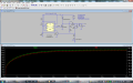
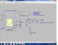
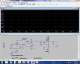
Electromagnet waveform

Thread Starter

cmartinez

Joined Jan 17, 2007
8,763
It doesn't look like it has an A to D converter. You will need one to do the pwm.
No, it doesn't have an A2D converter. But we don't really need one, we could use a comparator for that purpose, which we can perfectly adjust in real time using a simple pot configured as a a voltage divider. And if we end up needing an A2D converter anyway, I'm very familiar with several standalone types (8 bit to 16 bits) that we could use. As for the PWM, I know how to generate those pulses, no problem.
 

ronv

Joined Nov 12, 2008
3,770
You may be right. When I looked at this picture I thought they might be following a curve to get to the same current in the same time.


But you may be right the duty cycle may just change with the current.
 

Alec_t

Joined Sep 17, 2013
15,119
Since this machine sometimes works 24/7, my guess is that those small voltage cutoffs are there to keep the valve's coil at a low temperature as possible. And by the way, the plateau in my original measurements has several bumps going to 0 volts
Seems plausible. But care would have to be taken that the cut-offs were very brief, otherwise the valve would close prematurely. And if a lower current can still keep the valve open, why not use that lower current throughout the plateau for greater power saving? It's a mystery.
 

Thread Starter

cmartinez

Joined Jan 17, 2007
8,763
Hello again @ronv. Before I start asking questions about the details of your latest driver design, I'd like to show you my plans for the power supply.

For this purpose I'm considering a circuit that you so generously helped me design in a previous thread, and that I tweaked a little to make it generate the voltage that I need.
I changed the value of a few components, but the main one is the inductor, that I changed from 33µh to 220µh. Its datasheet says that its current rating is 5.5A (I'm getting 3.335A RMS in the simulation) and a saturation current of 8.7A (I'm getting 7.8A peak in the simulation, at least after the circuit stabilizes after the first 0.1 ms) I also changed the resistors at the 555, to make it work at a different frequency from the one originally planned.
Now, the waveform starts at 0A and peaks at 8.5A in 0.0005 seconds, after which a different voltage supply kicks in and gets in charge of generating the necessary current in the waveform's plateau.
A good friend told me that according to the current measurements that I did, and assuming an extremely worst case scenario of the cycle repeating every 12ms (which it won't, it will actually be closer to 20ms) we're looking at a 4.2% duty cycle on about 8 amps. Which means it's about 1/3 of a watt.

This power supply is delivering about 165mA @ 120 VDC continuously on a 750 load, which is almost 20 watts.

Will this do the trick? Do you think I should add more caps at its output?
 

Attachments

ronv

Joined Nov 12, 2008
3,770
Hmm, I had forgotten about that one.
It's a stretch, but it might work.
For the inductor - the number after the value is the saturation current. So you need to change that one too.
What I did was add a load to see what happens to the voltage when you hit it with the 5 amp pulse for 1/2 ms. As you can see it falls to 0.
The 120 volt supply only needs to deliver about 1/2 the total current the other 1/2 comes from the 12 volts when the 120 is off. Very cleaver.
Anyway I changed the inductor and the frequency to get the current up to recharge a larger cap in 20 ms.
When I did that it needed a delay in the start up because the inductor saturated charging the cap. So I added a delay in the reset line of the 555.
Then the start up current was still to high for the inductor I found, so I added a current limit - 2nd 547.
I'll play some more tomorrow.

Alec, The pwm works on current, so the current is still flowing thru the flyback diode during the off time of the pulse. So it is just on at like 3.3 amps and off at 3.5,
 

Attachments

Thread Starter

cmartinez

Joined Jan 17, 2007
8,763
Hmm, I had forgotten about that one.
It's a stretch, but it might work.
For the inductor - the number after the value is the saturation current. So you need to change that one too.
What I did was add a load to see what happens to the voltage when you hit it with the 5 amp pulse for 1/2 ms. As you can see it falls to 0.
The 120 volt supply only needs to deliver about 1/2 the total current the other 1/2 comes from the 12 volts when the 120 is off. Very cleaver.
Anyway I changed the inductor and the frequency to get the current up to recharge a larger cap in 20 ms.
When I did that it needed a delay in the start up because the inductor saturated charging the cap. So I added a delay in the reset line of the 555.
Then the start up current was still to high for the inductor I found, so I added a current limit - 2nd 547.
I'll play some more tomorrow.

Alec, The pwm works on current, so the current is still flowing thru the flyback diode during the off time of the pulse. So it is just on at like 3.3 amps and off at 3.5,
Play some more? Your circuit is working perfectly, at least from my perspective.
  • 1/4 second startup time... no problem
  • RMS at the inductor is 3.5A, with 9A peaks, except for a peak of 72A in the first few microseconds on startup.
  • R8 seems to be dissipating 3.4A RMS, that's about 1.16W (right?) so a resistor of at least 2W (preferably 5W) is in order (right?) What's R8's purpose, anyway?
  • Shouldn't we add a TVS to M1 to protect it a bit?
  • The mosfet that you picked turned out to be an expen$ive piece of jewelry ($17.58). The current through it never goes beyond 19A (RMS 3.8A), and drain to source voltage never goes beyond 130V, is it alright if I were to use this one instead?
I didn't change anything about your circuit, except the inductor's parameters, and change its file name. Also, I moved and stretched the components around to de-clutter it a little.

Anyway, this is the inductor I chose from Digikey, did I plug in the values correctly in the sim?

Here are other options that I considered for the mosfet:
 

Attachments

ronv

Joined Nov 12, 2008
3,770
Play some more? Your circuit is working perfectly, at least from my perspective.
The thing that worries me is that it is kind of on the edge. Notice the voltage doesn't have time to fully recover to it's starting value.


[*]RMS at the inductor is 3.5A, with 9A peaks, except for a peak of 72A in the first few microseconds on startup.
I think I got this a little better, but I would still buy the next size up in the inductor - They say they have 1 in stock.
[*]R8 seems to be dissipating 3.4A RMS, that's about 1.16W (right?) so a resistor of at least 2W (preferably 5W) is in order (right?) What's R8's purpose, anyway?
If you look at the average current it's only about 375mw once it is started, so a 1 watt is probably ok. It's purpose is to sense the current thru the FET (and inductor) to keep the inductor from going into saturation and blowing the FET. Once the voltage across it gets above about .6 volts the transistor turns on and holds the duty cycle there to limit the current. So it works the same way as the other one except for current instead of voltage.
[*]Shouldn't we add a TVS to M1 to protect it a bit?
Good idea.

I think we can use the same FET as we used in the other circuit - cheaper by the dozen.
I added a couple of part numbers and did a simulation at low 12 volts and at 20 and 40C.
I think tomorrow I'll look at one like you posted with the transformer.
[/QUOTE]
 

Attachments

Thread Starter

cmartinez

Joined Jan 17, 2007
8,763
Yup... startup is definitely better, peaking now at only 40A.
What do you mean pick a larger size inductor? You mean larger in its current handling capability?
 

Thread Starter

cmartinez

Joined Jan 17, 2007
8,763
So it's a centered tap input 115/230 VAC with a single 12VAC output, but the secondary is connected to the 12V side, while the primary is being used as an output?

EDIT: maybe a better description would be double coil input and double coil output, with its secondary connected in series and centered tapped, and its secondary connected in series.
 
Last edited:
Top