Effect of blocking Inlet / Outlet of Diaphragm Pump

Thread Starter

van53

Joined Nov 27, 2011
90
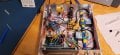
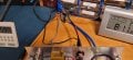
For a DC Diaphragm Pump such as this

If one completely blocks the inlet (vacuum/negative pressure) would this damage the pump?

What about completely blocking the outlet (exhaust/positive pressure) ? If so, what about for a short repeated duration of up to 500mS?

A pump similar to this is within the VP-30L Vacuum Pump by JoanLab which I have. I am using solenoid valves to control the air flow to be used for an SMD pickup tool and solder paste dispenser. I find for a thicker paste viscosity, 500mS of positive pressure is required for dispensing. I am curious about potential damage to the pump when under load by the solder paste in the syringe (3cc with plastic conical tip).

I asked this question to a colleague and they inquired about the length of hose connected to the pump (which will probably be around 5 feet) as they believe this may mitigate against damage to the pump for a short period of time such as 500mS if the pump is working close the its capacity. Thoughts?
 

LowQCab

Joined Nov 6, 2012
5,101
Provide a Storage-Vessel to store the ~5-Bar, (73-psi), Pressure that the pump is rated for.
An Air-Pressure-Switch on the Storage-Vessel should cycle the Pump "Off" at ~5-Bar,
and back "On" at a Slightly lower Pressure.
This will prevent "Short-Cycling" of the Pump, extending it's Life-expectancy.

A first-guess on the recommended size of the Pressure-Vessel is around ~20-Cubic-Inches.
A piece of 2-Inch PVC-Schedule-40-Pipe should make a fine Pressure-Vessel.

A Pressure-Regulator before the Output-Solenoid-Valve will help to keep operations consistent.

The Pump should be able to last, continuously Powered, for at least several Days,
under the above conditions.
We have no idea about the quality of the Pump,
or the Motor,
or if it has any recommended Duty-Cycle limitations.

You never really know what you're getting when You buy cheap Chinese stuff.

Blocking the Inlet for short periods "should-not" harm anything,
but could lead to over-heating of the Pump's Components and Seals,
causing failure if left running continuously in this condition.

There is no good reason for blocking the Inlet.

.
.
.
 

Thread Starter

van53

Joined Nov 27, 2011
90
Provide a Storage-Vessel to store the ~5-Bar, (73-psi), Pressure that the pump is rated for.
An Air-Pressure-Switch on the Storage-Vessel should cycle the Pump "Off" at ~5-Bar,
and back "On" at a Slightly lower Pressure.
This will prevent "Short-Cycling" of the Pump, extending it's Life-expectancy.
My pump in this case would be acting like an air compressor, where some pipe/storage vessel would be holding the compressed air at a given pressure? Is this needed in my case?

Currently I have multiple solenoid valves, the first a 4/2 valve switching between positive and negative pressure as needed (venting the one not currently used so as not to block it). The second solenoid valve is a 3/2 so that when closed (foot switch not pressed) the positive or negative pressure exhausts so as not to block the airflow and I can leave the pump on continuously in this case as I figured turning it on and off would reduce its lifespan. The final 3/2 valve is to let out pressure from the syringe or vacuum pickup tool when the foot pedal is not pressed.

If I feed the positive pressure directly to the syringe without a storage vessel then I must not exceed 73psi? I am guessing in this case I would need some gauge such as this on the output to monitor? Not sure if it will register the pressure properly in the 500mS timeframe ...

Is there any bearing on the approximate 5ft of 4mm inner diameter tubing between the pump and the final solenoid valve output where perhaps this tubing acts as a buffer for the 500mS of load ?
 

LowQCab

Joined Nov 6, 2012
5,101
This is sounding like You are setting-up a Production-Line.
The Pump(s) that You have selected are NOT going to stand-up to Production-Line-Duty.
You should go with Brand-Name, Industrial-Duty Pumps, such as "Gast" brand Pumps.

"" My pump in this case would be acting like an air compressor,
where some pipe/storage vessel would be holding the compressed air at a given pressure?
Is this needed in my case? ""
While it's not absolutely "required",
it will substantially reduce, or eliminate, the inevitable fluctuations in pressure delivery.

If a Vacuum-source is also needed,
it would also be a good idea to run a separate Vacuum-Pump, and
a Vacuum-Reservoir similar to the Pressure-Pump setup.

"" If I feed the positive pressure directly to the syringe without
a storage vessel then I must not exceed 73psi ? ""

The Pump that You have selected is claimed to be able to
produce 5-Bar, which is equivalent to 73.5-PSI
It is not likely to actually achieve this pressure, ( if You actually "need" it ),

and,
if it can actually achieve this pressure,
it may take an excessively long run-time to do so,
leading to over-heating, and possible early failure.

"" Is there any bearing on the approximate 5ft of 4mm inner diameter tubing between
the pump and the final solenoid valve output where perhaps
this tubing acts as a buffer for the 500mS of load ? ""
Yes,
but this is not a sound plan.
This plan is going to cause "Short-Cycling" of the Pump,
and/or,
possible substantial Pressure / Vacuum fluctuations,
and/or,
the Pump(s) should not be left running continuously and "Dead-Headed" against the Solenoid-Valve.
.
.
.
 

Thread Starter

van53

Joined Nov 27, 2011
90
This is sounding like You are setting-up a Production-Line.
The Pump(s) that You have selected are NOT going to stand-up to Production-Line-Duty.
You should go with Brand-Name, Industrial-Duty Pumps, such as "Gast" brand Pumps.
This is a hobbyist level project. I've seen small pumps such as these used and here . In this video it appears the pump is constantly being turned on and off. I am assuming this results in more wear on the motor? In my case I have the pump continuously on and only cycle the solenoid valves to open and close. When the solenoid valve closes the pumps airflow to the syringe/vacuum pickup tool it redirects it to an exhaust so it isn't (what I believe you are referring to as) "dead-headed". There is also this example which I am assuming is using a smaller pump however I am unable to obtain photos of the inside.

While it's not absolutely "required",
it will substantially reduce, or eliminate, the inevitable fluctuations in pressure delivery.
For several commercial solder paste dispensers I've seen on YouTube they do as you mentioned and use an air compressor / reservoir. With using the pump directly without a reservoir I have to keep the on time longer before paste can be dispensed vs what I have observed in videos of the commercial units so I think if I originally designed it as you mentioned this would not be the case. This individual appears to have done what you suggested regarding a pipe for a reservoir.

As it stands right now (with no reservoir), the vacuum pickup tool works well. The concern I have is with the solder paste dispenser and the paste causing a load against the air flow and *potentially* damaging the pump. As you mentioned no detailed data for the pump is given so if I choose to use the pump in this fashion I guess the result is unknown...

I was able to switch to a lower viscosity paste. Earlier the issue with the lower viscosity paste was that it would keep flowing even if the pressure in the line/syringe was exhausted. This wasn't enough so I added the ability to switch from positive to negative pressure for some pull back. It appears to work well in this condition and there is no more running of the paste. I found that if I set the positive pressure for about 235mS and then switch to negative pressure for about 350mS it worked well for the paste I tried. In this case I was about to reduce the load on the pump when operating with positive pressure from 500mS (higher viscosity paste) to 235mS (lower viscosity paste) but again not sure what the end result would be on the pump itself ….

I am guessing the way to tell if I wish to keep it in this configuration is to add a gauge near the output on the syringe line using a T adapter and see how much pressure is actually building up in the line and then compare against the pumps specifications of the advertised 5 bar rating?
 

LowQCab

Joined Nov 6, 2012
5,101
I evidently misunderstood the application.

I can't tell You anything about your Pump,
other than,
even with ideal conditions,
it is not designed to last very long,
especially when operating near it's limits.
But, that's probably acceptable for limited, occasional, Hobbyist use.

Heat is going to be your A#1 enemy.
And, compressing Air always generates Heat, ( for the Pump, and for the Motor ).
Pulling a Vacuum is hardly ever a problem, with the exception of Heat, ( friction ), in the Bearings.

Make sure to regularly put a single, small, drop of Oil on all the Bearings.
.
.
.
 

MaxHeadRoom

Joined Jul 18, 2013
30,557
What is the exact nature of the pump , i.e. radial? Axial impeller ? gear? vane.
For example, blocking either inlet or outlet of either former two above usually results in a drastic reduction in load. depending on type.
e,g, listen to the motor on a typical vacuum system motor ,RPM drastically increases when outlet is blocked. due to load reduction which is maximum with no inlet and outlet hose.
 

Thread Starter

van53

Joined Nov 27, 2011
90
What is the exact nature of the pump , i.e. radial? Axial impeller ? gear? vane.
I am unsure. It is listed as a NBR (Nitrile Butadiene Rubber?) Diaphragm pump. Likely very similar to this as a portion of the part number on it matches what was found inside the JoanLab VP-30L which is the one I have. It runs on 12V DC. I recall that when the vacuum is blocked the current decreases and doesn't increase which to my understanding is charteristic of diaphragm pumps.
 

Tonyr1084

Joined Sep 24, 2015
9,744
In my case I have the pump continuously on and only cycle the solenoid valves to open and close.
Is there a reason why you don't just switch the pump motor ON and OFF with a foot pedal as opposed to constantly running it and using solenoids to dispense solder paste? Or in the case of the need of vacuum?
What is the exact nature of the pump , i.e. radial? Axial impeller ? gear? vane.
My "Assumption" is that it is a diaphragm pump with flapper valves. I've seen that sort of thing before, and I even have a much larger diaphragm pump of my own. I use my pump to drain fuel from gasoline tanks in my yard equipment in some cases and in other cases I use it to stick a 1/4" tube down the dip stick pipe to evacuate used motor oil. This is always done outdoors with 100% ventilation so no danger of gasoline fumes and switches sparking a fire.

IF this is a diaphragm pump blocking off the inlet (vacuum side) it will increase the load on the motor. From what I saw looking at the picture, the pump in question isn't meant for heavy duty operation. While the idea of a reservoir (tank) for pressure is a sound piece of advice, I don't see a need for such. But one thing does stick in the mud on running the pump only when dispensing is the fact that residual air pressure in the line will continue to flow paste until the pressure equalizes. Since you HAVE solenoid valves you might be able to set them up as pressure relief valves to dump the excess pressure when done dispensing the paste. Run the motor - build pressure - dispense paste - stop the motor - dump the remaining pressure - paste stops flowing.

Another alternative you might consider is running the pump continuously and have an open tube teed off of the feed pipe to the syringe (paste dispenser). Place your finger over it and paste flows due to the pressure in the pipe. Remove your finger and pressure is released, thus stopping the flow of paste.
 

Tonyr1084

Joined Sep 24, 2015
9,744
Screenshot 2025-04-08 at 6.43.09 AM.png
Foot pedal when motor needed.
Waste port - place finger over port - dispense paste.
Foot pedal off when done - remove finger from waste port - paste stops flowing.
 

Thread Starter

van53

Joined Nov 27, 2011
90
Is there a reason why you don't just switch the pump motor ON and OFF with a foot pedal as opposed to constantly running it and using solenoids to dispense solder paste? Or in the case of the need of vacuum?
I could but I thought the continuous on and off every couple seconds would cause more strain on the motor vs just leaving it running continuously for some time (e.g. 30min - 1hr).

But one thing does stick in the mud on running the pump only when dispensing is the fact that residual air pressure in the line will continue to flow paste until the pressure equalizes. Since you HAVE solenoid valves you might be able to set them up as pressure relief valves to dump the excess pressure when done dispensing the paste. Run the motor - build pressure - dispense paste - stop the motor - dump the remaining pressure - paste stops flowing.
Running the pump continuously I came across the same issue. When the foot pedal is not pressed the first 3/2 solenoid valve (within the enclosure) blocks the airflow and vents to the exhaust so the pump isn't dead-headed. The second 3/2 solenoid valve (within the enclosure) exhausts the pressure in the line when the pedal is released (this would be the automatic implementation of the waste port you described to my understanding). This worked well for the vacuum pickup tool as even though I had a small hole in the pickup tool handle it was not large enough to release the vacuum quickly when the pedal was released and components would stick for a while. When dispensing high viscosity solder paste for 500mS you could hear the pressure audibly whoosh out from the exhaust/waste port of the second 3/2 solenoid valve when the pedal was released. When low viscosity paste was used, exhausting the pressure was not enough, I needed to switch to vacuum and pull back (negative pressure) for some period of time...

I've attached a picture of the final outcome. The solenoid valve outside of the enclosure is the one which was originally meant to be run on AC and it is running on DC. It switches the main line going into the enclosure between positive and negative pressure as required.

I guess I will see how things works out with the 235mS cycle load on the pump when using low viscosity paste and if it results in any damage to the pump...
 

Attachments

Thread Starter

van53

Joined Nov 27, 2011
90
Curiosity question: What is a 3/2 solenoid?
I am no expert but in my learning of solenoids valves for this project a 3/2 valve has three ports and two states. The diagram on the valve indicates the two states, one with the spring is the off or default state and the other with the solenoid diagram would be the energized state (to my understanding). There are also arrows on the diagram indicating flow direction however in my communication with MAC the 3/2 direct acting valves I used can be connected in any direction as opposed to pilot activated valves where direction matters and some minimum air flow is needed (if I understand correctly)
 
Last edited:

Thread Starter

van53

Joined Nov 27, 2011
90
Earlier I was asking about measuring the maximum pressure in tube going to the syringe. I was concerned that the pressure may occur so fast and was unsure if the gauge will read it. If we look at the diagram provided by Tonyr1084 , where the waste port is labeled: If we connect a check valve at that point such as this and then to the meter I linked earlier. I am thinking that the air pressure will flow through the check valve to the gauge and will not be allowed to return therefore causing the gauge reading to show whatever the maximum pressure that was in the line. Would this work?
 

Tonyr1084

Joined Sep 24, 2015
9,744
If I understand your question (though probably not) you want to measure the pressure at the vent side, which would only measure the pressure AFTER the foot pedal is released. Based on that premises I'd say that wouldn't work. The reason why I'm saying it wouldn't work is because air pressure is in part related to volume. If you have a 1 inch non-pressurized tube with a gauge on the end and you open it to residual pressure - as the air fills that void the pressure will drop slightly. But if the tube is 10 inches, as that residual air pressure flows into the tube for measuring since the volume is greater the pressure will drop further, thus changing the reading to a lower value. In other words, the same amount of air in a contained space at a given volume (space for that air) the pressure will be 1X. But in a volume who's twice the size you would see 0.5X. Or maybe 0.25X pressure. Remember, this is the same volume of air versus the container holding that volume.

When I was a kid I took an empty coke bottle into a pool. Went down about 4 feet and allowed air to escape from the bottle until it achieved neutral buoyancy. As the bottle slightly rose the pressure dropped inside the bottle and the volume expanded, causing the bottle to rise faster and faster. But if the same exact condition in that bottle were moved slightly lower than its neutral buoyancy point the bottle would sink to the bottom of the pool. Same amount of air, different space occupied by that air, changed the result.

And thanks for the info on 3/2 valving. Bertus linked to confirm what you were saying.
 

Tonyr1084

Joined Sep 24, 2015
9,744
Looking for it but can't find it - I've seen an autonomous sub that rises and lowers simply by expanding and collapsing an air chamber. No change in the volume of air, just the space it occupies. This sealed volume can be expanded or collapsed causing the sub to rise or sink. Its fins propel the sub simply by the rising or sinking of the sub. Once the chamber has been expanded there is less water weight inside the sub and it rises nose first. This moves the sub forward. As the chamber is compressed more water fills the sub and it sinks nose first. This also moves the sub forward. So with very little energy the sub is able to propel itself through the water using only the energy it took to change the size of the chamber. No air is pumped in or out of the chamber, it's the change in the space it occupies. Same as the coke bottle in post #17. Mechanical energy is expended for the moments it takes to move a piston forward or back. Once the change has been accomplished (via battery power) the sub now moves with no further use of energy. Not until it reaches a pre-programmed depth when it changes direction up or down.

I know this is off subject - sort of - but I'm bring this up only to help understand how the length of a tube, long or short can hold the same amount of air at different pressures. This is why I say you measuring the vented air pressure won't work. Not to mention that venting into a gauge won't release the pressure, and that pressure will continue to push paste out of the syringe.

To gauge the air pressure in the tube it must be done with a consistent amount of pressure. As the syringe pushes the paste out that air pressure must remain the same. Changing that pressure will cause the paste to flow faster or slower during the time it's pressurized.

The dispenser units I've seen have a pressure regulator that shows the amount of pressure setting before the control valve. If the operator desires a faster dispensing of paste they would turn up the pressure. Slower would require lower pressure. That has been the method for controlling the flow of paste in units I've seen and used.
 

Thread Starter

van53

Joined Nov 27, 2011
90
you want to measure the pressure at the vent side, which would only measure the pressure AFTER the foot pedal is released.
I think I confused things by using the waste port reference in my question ...

I want to measure the pressure going into the syringe while the foot pedal press triggers the positive airflow (air flows for the time set by the operator, e.g. 235mS once the pedal is pressed). I still plan to keep the second 3/2 solenoid in place to vent when the pedal is lifted (it actually starts to vent regardless if the operator keeps their foot on the pedal and rather once the set time has elapsed). What I was thinking about doing is splitting the tube that is connected to the syringe and branch off just before the syringe. I attempted to use your graphic for this idea..

I was thinking that if I put a T connector so that the tube goes to the syringe but also splits off just before the syringe to a check valve and then to a gauge. My idea was that when the pedal is pressed and the positive air flow cycle begins, it will flow to the syringe and also into the check valve to the meter. Pressure would build up in the syringe and within the tubing past the check valve. Then when the cycle of positive pressure is finished (e.g. 250mS) the pressure would be released from the syringe via the vent in the solenoid but the pressure that built up past the check valve would be maintained as the check valve would not(?) allow the pressure to flow back and the gauge will read the maximum pressure that existed in the syringe (or something close to it?)...
 
Last edited:

Tonyr1084

Joined Sep 24, 2015
9,744
That would work. Only, suppose the operator set the pressure at 35 PSI the first time and then set it to a lower pressure after discovering that too much paste was flowing too quickly. Once the 35 PSI has reached the gauge and is locked there, you have no other way to release that pressure unless you install a hand valve or a solenoid to relieve that pressure.

I've seen gauges (torque gauges to be exact) with a max needle that is pushed to its max position. Even after the torque is released the max needle remains stationary. The operator would then have to set it back to zero. THAT could work if they make such a meter with the max pointer.
 
Top