Hi Les, again thank you for your insight and help in this whole project. I have learned so much from you that isn't told in the books I have. I'll make those other changes you talked about and repost the drawing.
Hi SB, Hi Les , I have planed to change my circuit as given in thread#123 from using zenor diodes and transistors to use op-amp and a logic IC. As I find that by using op-amp I may have more easier to adjust set voltages. But look like foot print on circuit board are about same. But would it come at cost of speed? Would yall mind take a look and comment, please.
Hi Roong. I don't know much about opamps so can't answer to that. But don't understand why your even using an opamp to do a comparators job. I know they are basically the same thing, but a comparator is better suited to do the job of a comparator, that's why they were developed in the first place and have been more popular in circuits needing a comparator. Just my point of view, not a criticism, like the way you use a stepper, if it works for you go for it.
A question, why are you using 200V as an open circuit voltage? While it really won't hurt anything, it will make the "over burn" of the electrode twice the size of the normally used ~100V, which is the area most industrial machines use. That, 100V number came from trying to get square corners in the cavity being burned and still allowing good flush in the burn. At 100V you get a 0.001 to 0.0015 inch over burn, which makes for most jobs being done a square enough corner. Again, what ever works for you.
SB, My LM393N is a comparator not an op-amp. And 3 outof 4 of LM4558 are use as buffers (another word voltage followers). The last LM4558 I use it to replace two p-transister in LesJones current mirror.
I have my main transformer which only give 100V DC. Another tiny transformer of may be 190VDC is connect in pararell. Just to have high break down votage then main transfomer will take over. This method I v found to be used by a Taiwanese machine, if you measure at electrode you find 220vdc but once it hitS the job voltage reduce to 90V. 220V can only shock you but not dangerous because only few miliamp at most. It just help sensing circuit to detect ealier ,I believe.
As you can see that maximum upper threshold of my circuit is just only around 89V.
Hi roong,
It looks good to me. I don't think there will be any significant loss of speed. You have missed the loop where the 0 volt power to the third op amp from the left crosses the input to the window comparator. (It looks like the input is shorted to 0 volts.)
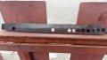
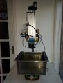
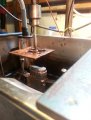
Looks like you got it working! Would really like to see some pictures of the machine with good lighting. Was trying to figure out what the things up near the motor are, at first they looked like a wind chime
That was good lighting but my samsung was sucked I will try it later on, the motor was Nema17. I was using diesel so it sounded bad. You may see the small hole( a quater inch dia in the file). That was done three year ago, It took me 5 1/2 hour, since then it had been constantly improving, my latest was 12mm hole. and I can do it in 2 1/2 hour (The file was 7 mm thick). My electrode was a copper rod with tip had been erode so it look sharp at the end. It took me almost 1/2 hour to make through hole pass the file. But to enlarge it to 12mm took almost two hours. I don't think i can make it much faster than this. Before the end I must adjust frequency from 9000Hz to 19000Hz otherwise surface look bad. My duty cycle was just 30%, wont allow to more than 50% because I am using SG3525. I think ,may be wrong, that without submerge system I can't cut it too aggressive because breaking fire.
By the way it is nice to here from you again.
Hi Roong, I know it doesn't seem logical, but by making the size of the steps your motor is taking smaller will decrease the burn time.
Your lead screw looks pretty coarse. And I don't know what you are using for a stepper motor driver. but you should be using one that allows "micro stepping". The way it looks in the video you posted, your machine is spending a lot of time retracting. That is not what you want it to do. You need to find out the pitch of your lead screw and then try to find the micro step that allows the electrode to only move forward/down no more than the "over burn distance" with each step. If the ram moves more than the over burn distance with each step, it will contact the work and cause a short circuit that will make the ram back up. And when the ram is going up, there is no metal being removed, just sparking on the side wall of the cavity. So, by making each step of the motor smaller in distance you will not short out as much and the actual cutting speed will be faster.
In sinker EDM speed is controlled by metal removal, not the actual speed that the lead screw rotates, it is completely the opposite of every other type of machining way of doing things.
@roong, can you post a circuit of the power supply you're using to generate the sparks?
I think I already understand the logic behind the motor control. What you're doing is using a "window comparator" in which the motor feeds the electrode if the voltage is too high, and retracts it if it's too low. Isn't it?
Hi Short bus, my lead screw is 10mm and 2mm pitch trapizoidal japs ' one I bought bronze lead nut online from England. I agree with you that it a bit crude, but not that what you think but once you have it you must try to use it , can't change it back and forth. It costs money though . My system once spark is detected. It almost stop for a predetermine time , it actually regulates around 94V, time setted by a dip switch, after that it retracts for a predetermine hight, hight is also setted by another dipswitch. My retract is to remove debris. I understand that I must avoid short circuit because it ruins electrode , even though it penetrate faster. My system isn't just short then retract and when recharge plunge.
Hi Cmartinez, now I regret using comparator op-amp to detect voltage, and now consider switching back to use zenor diode like I used to do. First it looks precise that you can adjust to any fine voltage but in reality how do know you voltage value at pin6 of op-amp and it is not translated directly to spark voltage. I use two small 20 turns blue trim pot. After i make a few turns I forgets which way I did turn. Then you have to measure pin6 and compare to a chart and its location is very close to HV it detects, not so funny. I once made mistake swapt poles of high voltage. It was difficult to determine which one that burn. With zenor diode circuit you can readily check which one broken. And zenor you can also adjust voltage by 6 volt step using DIP switch. And easy to know which voltage you were before by looking at DIP switch. Afterall my machine is intended to be at a corner of a garage not to compete with Argie-Charmills.
Hi Cmartinez again, To design power supply not a good point of me, I use SG3525 which limit duty cyle to 50% or less which I consider enough for homemade like me. Power supply of my SG3525 is 16.5V, -16.5V (using a seperated small transformer 12ac,0,12ac) one of the two outputs of SG3525 drive a totem pole of transister (I use conjugate MUJ2995 and 3055 (TO248) This in turn drive gates of three IRFP260 (TO220). Some people in the net said this totem pole is unnecessary cause SG3525 by itself be able to drive all the Gate of. IRFP260.
The Moosfets turn on and off at a ground of the circuit not at 100v. And for frequency adjusting I have a DIP switch to select R and C and I have table to tell the freq and position of DIP switch, the freq are 4K, 8.9k, 11k, 19k, 25K, 35k, 68k. That is it.
I’ve visited this thread a few times for the past few months and I thought that it had died but I’m glad to see that it’s been active lately so I thought I would tell you about my surprisingly successful edm build and throw a spanner into the works so to speak for which I’ll apologise now for.
I’ve been a die sinker and toolmaker all my life and have over 40 years experience with edm and after being made redundant a while back I decided one day over a pint at the local with a friend of mine that I could probably build an edm as I have a basic understanding of edm workings and in electronics, so the challenge was set.
At first I thought that the actual generator was going to be the problem for me as I could see online in forums and in videos that people seemed to struggle with the concept of how they work, using multiple logic circuits to monitor this, that and the other but the fact is that a proper pulse edm generator is very easy to build and the most amazing thing is that apart from the high (100v dc) voltage side, and the power transistors used to switch the high voltage on and off in time/ frequency and as an exact copy of the waveform set by the user’s setting, is that all the modules required to build an edm (square wave frequency generator, timer unit to lift head for flushing etc and head motor control unit) are all available cheaply online! All you have to do is wire them all together and it works!
I’ll try to post some pictures of the machine and generator I built from an old drill stand and pc case and one of a small press tool punch part eroded.
The machine was made on the cheap as I thought it wouldn’t work (less than 300 pounds/ dollars in total but some components I already had) using a couple of those awful Chinese cheap x y tables but hey it works and at the time I didn’t have access to any proper machinery but on the plus side you can pick it up with one hand and shove it in a cupboard after use!
The edm is comparable with commercial machines in both stock removal and electrode wear as well, which surprised me.
Another couple of bonus features is that it can spark both downwards and upwards (swap round the motor leads) which is useful for backing off a tool bed (there’s two head limit switches fitted) and because the head drive motor can be lifted off easily, if you make an offset rig for the v block and by using a brass or copper threaded bar and matching nut and connecting the head drive motor to it, you can spark threads!
I apologise again for not posting sooner but I hope this will inspire you to rethink your edm builds, you don’t need to use stepper motors (they will work but you’ll need an extra motor control unit) or any complicated logic circuits, just keep it simple and it’ll work.
Hi EdmGuru, welcome to the thread. As there are more things to do outside during the northern hemisphere summer, I haven't done much lately. But did get my power board etched, because I won't etch indoors. And after the weather changes again there should be more traffic, at least from me.
My first idea was to do it similar to you. But after running Charmilles machines for a long time I wanted something that was more like their "Isospark". Hopefully it will work as planned.
Please, as it is my thread, feel free to post any of your schematics or other things you want. There is too many doing this that want to keep it secret, or profit from their way of doing it. Knowledge should be shared.
[QUOTE="EdmGuru, , you don’t need to use stepper motors (they will work but you’ll need an extra motor control unit) or any complicated logic circuits, just keep it simple and it’ll work.
Cheers.[/QUOTE]
Hello Mr.Edmguru , I paid less than 6 pounds for stepper motor driver from ebay... it come with free dilivery from china. Also I bought Pololu4988 for around 1.5$ but you have to make interface board for that 4988. Also I have used driver for 5 phase Vextra cost me around 5 pound. Everyone works. With stepper motor changing direction is also easy.
The most expensive and time consuming for me is flushing system. I still using diesel with moped motor pump. I cannot think of another cheap way.
Hi roong,
I use paraffin as a dielectric as I find that's it's the best also the cheapest over here in the UK. Also diesel has additives in it I believe to stop it from waxing up at low temperatures like we get over here so it mightn't be as good? I don't know I haven't tried diesel but I have used/ tried vegetable oil in the past (not recommended) but it turns and remains black quickly also everything is covered with a sticky coating afterwards.
Apparently you can use white spirit as a dielectric but you must keep it cool and the work piece submerged at all times because of the flash point.
You can also use water as a dielectric like they do on a wire edm but it will only really work at low amps and it needs to be constantly deionised through deionising resin which is a pain, also it will erode better with brass rather than copper electrodes.
I hope this helps.
Cheers.
They tried that where I worked, for a while. Works good in wire but not in sinkers. The sinkers produce so much debris it clogs the deionizing tanks, even if filtered first.
They did use water in the 'hole shooters' but it was a total loss system, straight down the drain after use, not recycled.
 Facebook
 Google
 GitHub
 Linkedin
")