Can we cancel rotor reactance of Wound Rotor Induction Motor by adding capacitors in series electrical resonance.

Thread Starter

70Miles

Joined Dec 28, 2025
14
Hi,

My question is about Wound rotor induction motor.

Can we cancel rotor reactance of WoundRotor Induction Motor (or other Induction Motor) by adding capacitors in series electrical resonance.


What happens to equations for :
-Rotor induced emf
-Rotor iduced current
-Torque
of Wound Rotor Induction Motor ( WRIM ).

I' ve got the following answer (from Chat GPT4) :


-----------------------------------------
At resonance condition ,when sX2 = XC:
(X2-Rotor Impedance at standstill for original WRIM without added capacitors)
(XC-Impedance of Added Capacitors)
-----
Rotor induced Emf ->Unchanged E2(s) = sE2
Rotor Induced current -> Changed
Torque -> Chaged
-----
Please see attached file : Induction Motor Rotor Circuit Chat Gpt 4.pdf


-----------------------------------------

Is it True?

Thank you
 

Attachments

MrChips

Joined Oct 2, 2009
34,747
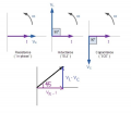
The impedance of an inductance L is,
ZL = jωL

The impedance of a capacitance C is,
ZC = 1/(jωC)

At resonance,
ZL = ZC

Hence,
jωL = 1/(jωC)
or
ω^2 = 1/(LC)

1779716287903.png

The impedance of L is the opposite phase of the impedance of C. Hence the impedances cancel at resonance.
 

Thread Starter

70Miles

Joined Dec 28, 2025
14
The impedance of an inductance L is,
ZL = jωL

The impedance of a capacitance C is,
ZC = 1/(jωC)

At resonance,
ZL = ZC

Hence,
jωL = 1/(jωC)
or
ω^2 = 1/(LC)

View attachment 367638

The impedance of L is the opposite phase of the impedance of C. Hence the impedances cancel at resonance.
Thank you for Reply

So according your answear :
It is possible to :
"
cancel rotor reactance of (WRIM) Wound Rotor Induction Motor (or other Induction Motor) by adding capacitors in series electrical resonance.
"
 

MaxHeadRoom

Joined Jul 18, 2013
30,627
What is the exact nature of the wound rotor Induction motor? What are you trying to achieve as to motor behavour?
BTW, all AC induction motors have a wound rotor, allbeit shorted turns in most cases.
There are then the versions that bring out the the rotor winding via slip rings, Purpose = varied.
 

Thread Starter

70Miles

Joined Dec 28, 2025
14
What is the exact nature of the wound rotor Induction motor? What are you trying to achieve as to motor behavour?
BTW, all AC induction motors have a wound rotor, allbeit shorted turns in most cases.
There are then the versions that bring out the the rotor winding via slip rings, Purpose = varied.
Thank for Answer
Please don't ask additional questions and only answer to initial question. Thank you.
 
Max:
Wound rotor induction motors are -now mostly obsolete- variable speed/ torque induction motors, used back when high performance VFDs weren’t available. The rotor itself had windings which were connected to slip rings and brushes. By adding or decreasing an external resistance in series with the windings, the slip characteristics of the induction motor would change, causing the speed and torque to vary.
They were used mostly on devices where torque and speed required a narrow adjustment range, such as hoists and sometimes in elevators, as the resistors were significantly cheaper than DC motor controllers.
 
To the TS: your proposed scheme doesn’t work.
For the simple reason that the slip frequency changes as the rotor speed changes. Resonance can only occur at a single frequency. Meaning that it will only occur at a single rotor speed. Which is kind of moot for a motor which one of its advantages is variable speed control.
 
Last edited:

Papabravo

Joined Feb 24, 2006
22,080
Possible or Not ? Further details are welcome , but only if you are certain.
Adding a fixed capacitance to your system may or may not help you. The value must be precise, and it must be temperature stable. Let me ask you some questions in return.
  1. What is the typical range of values for the capacitors you intend to use?
  2. What is the tolerance on the nominal value of those capacitors?
  3. How does the capacitance of those capacitors change with temperature?
Pick the wrong capacitor(s) and you will frustrate yourself trying to get something to work that cannot work under the existing conditions. I am quite certain about this.
 

Thread Starter

70Miles

Joined Dec 28, 2025
14
Adding a fixed capacitance to your system may or may not help you. The value must be precise, and it must be temperature stable. Let me ask you some questions in return.
  1. What is the typical range of values for the capacitors you intend to use?
  2. What is the tolerance on the nominal value of those capacitors?
  3. How does the capacitance of those capacitors change with temperature?
Pick the wrong capacitor(s) and you will frustrate yourself trying to get something to work that cannot work under the existing conditions. I am quite certain about this.
Thank you for your Reply.
I am asking most general case (concept) question.
Lets say I have ->Ideal/Perfect<- Capacitor

Two scenarios :
1. WRIM at standstill condition (Slip s=1)
2. WRIM is rotating at constant speed (constant slip s -> Only one particular value) condition
Is it possible ?
 
I have already responded to your question in post 9.
And yes, I am fully certain. I worked on a steel mill and there were literally hundreds of motors of all types and horsepower ratings.
 

Papabravo

Joined Feb 24, 2006
22,080
Thank you for your Reply.
I am asking most general case (concept) question.
Lets say I have ->Ideal/Perfect<- Capacitor

Two scenarios :
1. WRIM at standstill condition (Slip s=1)
2. WRIM is rotating at constant speed (constant slip s -> Only one particular value) condition
Is it possible ?
You still have a variable reactance to compensate for. How are you going to do that with a capacitor having fixed ideal value?
 

Thread Starter

70Miles

Joined Dec 28, 2025
14
I have already responded to your question in post 9.
And yes, I am fully certain. I worked on a steel mill and there were literally hundreds of motors of all types and horsepower ratings.
Thank you.
Just for clarification :

Two scenarios :
scenario 1. WRIM at standstill condition (Slip s=1)
scenario 2. WRIM is rotating at constant speed (constant slip s -> Only one particular value) condition
It is possible in both scenarios

using certain capacitors to cancel rotor WRIM rotor reactance as
mentioned in the initial question and attached document.
 
Yes, theoretically it could. But wound rotor induction motors are intended to be used as variable speed/torque devices.

So which condition would you select? Startup? Full speed? In between?
BTW, the full speed is never constant. It varies both with load and most importantly, external rotor resistance.
 

Thread Starter

70Miles

Joined Dec 28, 2025
14
Yes, theoretically it could. But wound rotor induction motors are intended to be used as variable speed/torque devices.

So which condition would you select? Startup? Full speed? In between?
BTW, the full speed is never constant. It varies both with load and most importantly, external rotor resistance.
Thank you.
scenario 1. WRIM at standstill condition (Slip s=1)
scenario 2. WRIM at constant slip s, constant speed, suitable for continious/stable rotation/operation (More than 1 hour lets say) without overheating and so on.
 

MaxHeadRoom

Joined Jul 18, 2013
30,627
Max:
Wound rotor induction motors are -now mostly obsolete- variable speed/ torque induction motors, used back when high performance VFDs weren’t available. The rotor itself had windings which were connected to slip rings and brushes. By adding or decreasing an external resistance in series with the windings, the slip characteristics of the induction motor would change, causing the speed and torque to vary.
They were used mostly on devices where torque and speed required a narrow adjustment range, such as hoists and sometimes in elevators, as the resistors were significantly cheaper than DC motor controllers.
I am very familiar with several versions of wound rotor AC induction motors, One rarely seen is very large, +100HP, these were 3ph synchronous motors that were brought up to speed as induction motors using the 60Hz supply they had a couple of slip ring where DC was injected at this point to the rotor windings and they then came up to syncronism.
 

MaxHeadRoom

Joined Jul 18, 2013
30,627
Max:
. The rotor itself had windings which were connected to slip rings and brushes. By adding or decreasing an external resistance in series with the windings, the slip characteristics of the induction motor would change, causing the speed and torque to vary.
I saw these use mainly in overhead cranes etc, often the 3 phase rotor windings were rectified and the DC fed the variable resitance-bank controller for speed control.
 
Top