Facebook
 Google
 GitHub
 Linkedin
Hello,
Is it convenient to ask a question about this article:
----------------------------------------------------------------------------
https://sciencedemonstrations.fas.harva ... ive-phases
More speciffic :
Case 1:
-------------------------------------------------------------------------
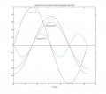
1) At resonance, the phasor representations of the inductive and capacitive reactances are equal in magnitude and 180˚ out of phase with each other. Thus the total impedance of the circuit is purely resistive and the current is in phase with the emf. The following graphic depicts the phase relationships between the various parameters, including the Lorentz force on the current in the coil. Since the Lorentz force is equal to the cross product of the current and magnetic field, the graph was generated by simply taking the product of the induced current graph and the magnetic flux graph. [Note that the magnetic field from the iron core actually diverges and the interaction responsible for pushing the coil longitudinally is with the radial component of the magnetic field through the coil; the longitudinal component generates the emf.]

The vertical scale is arbitrary, but nevertheless, one can see that the net force on the coil is zero in one complete cycle of the magnetic flux—it is as much negative as it is positive. When an appropriate capacitor is connected across the coil to make the circuit's resonance frequency equal to 60 Hz, the current is in phase with the emf and the coil is neither attracted to nor repelled by the magnetic field. [As a side note, this is exactly the reason why simply invoking Lenz's Law is not enough to explain the action of the Ring Flinger demonstration.]
-------------------------------------------------------------------------
----------------------------------------------------------------------------
If we replace the primary coil with AC source from this picture :
 With permanent magnet like linear generator configuration:
Does it means that there is no repulsive force :
I mean if we approach and move away the magnet to secondary coil in resonance state (so that the frequency dPhi/dt is with the frequency F and LC of the scondary coil is at resonance with that frequency).
Thank you.

I mean if we oscilate the magnet back and forth at resonant frequency.
Is it convenient to ask a question about this article:
----------------------------------------------------------------------------
https://sciencedemonstrations.fas.harva ... ive-phases
More speciffic :
Case 1:
-------------------------------------------------------------------------
1) At resonance, the phasor representations of the inductive and capacitive reactances are equal in magnitude and 180˚ out of phase with each other. Thus the total impedance of the circuit is purely resistive and the current is in phase with the emf. The following graphic depicts the phase relationships between the various parameters, including the Lorentz force on the current in the coil. Since the Lorentz force is equal to the cross product of the current and magnetic field, the graph was generated by simply taking the product of the induced current graph and the magnetic flux graph. [Note that the magnetic field from the iron core actually diverges and the interaction responsible for pushing the coil longitudinally is with the radial component of the magnetic field through the coil; the longitudinal component generates the emf.]
The vertical scale is arbitrary, but nevertheless, one can see that the net force on the coil is zero in one complete cycle of the magnetic flux—it is as much negative as it is positive. When an appropriate capacitor is connected across the coil to make the circuit's resonance frequency equal to 60 Hz, the current is in phase with the emf and the coil is neither attracted to nor repelled by the magnetic field. [As a side note, this is exactly the reason why simply invoking Lenz's Law is not enough to explain the action of the Ring Flinger demonstration.]
-------------------------------------------------------------------------
----------------------------------------------------------------------------
If we replace the primary coil with AC source from this picture :
Does it means that there is no repulsive force :
I mean if we approach and move away the magnet to secondary coil in resonance state (so that the frequency dPhi/dt is with the frequency F and LC of the scondary coil is at resonance with that frequency).
Thank you.
I mean if we oscilate the magnet back and forth at resonant frequency.