EDM - Electrical discharge machine

LesJones

Joined Jan 8, 2017
4,511
Hi SB,
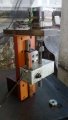
This is a design based on what bits I had in my junk box . The L298 was salvaged from a an old Pace satellite receiver. (It was used to drive the dish actuator.) I was explaining the schematic I posted in post #29 showing how I had modified the window detector Ben Flemmings version when we were discussing the things we disliked about his design. I posted the picture to show what a lash up it was. I do not suggest it is a design worth anyone else copying.

Les.
 

Thread Starter

shortbus

Joined Sep 30, 2009
10,050
Hi guys, forgot about that post#29. My use of a diode between the motor servo , was done to eliminate having two pots. This has been an ongoing problem for people running home made EDMs, getting the gap voltage consistent. One of my go to books on EDM theory, "Electrical Discharge Machining" by Elman C. Jameson, claims that the ideal voltage between advance and retract for the servo is ~5V. so that's what I based my circuit on. Jameson is claimed to be one of the "experts" on EDM and worked for some manufacturers in design, the book is an Society of Manufacturing Engineers published book, has the most information on EDM of any book I've found.
 

roong

Joined Feb 11, 2017
59
Hello Les, I think you only have one transformer to make all these 70vdc,16vdc, 12vdc, 5vdv, 0vdc and -12vdv. Do you really need to measure gap votage at it(gap) location, can you not only measure at a point just before DPDT switch .I mean on other side of switch to avoid complication of reversing signal when changing polarlity.
By the way, That piece of circuit is pritty elegrance, the one that except reverse polarity.

Hello SB,
Elman C. Jameson, claims that the ideal voltage between advance and retract for the servo is ~5V.
Do you mean the difference upper threshold and lower threshold to window comparator?
 
Last edited:

LesJones

Joined Jan 8, 2017
4,511
Hi roong,
The transformer in the diagram only provides the 70 volt supply. There is another 12 0 12 volt transformer to provide the + and - 12 volts and the + 5 volts. I have not drawn a schematic for this part. (This transformer is at the middle bottom of the picture. It is not very clear with reflections off the clear plastic cover which covers the mains terminals on this transformer.) If the gap voltage was measured before the DPDT switch then when electrode was the negative the work piece would be at +70 volts if the electronics common was connected to the mains ground. If the work piece was connected to ground the electronics common would be at - 70 volts. I thought it was worth adding a few extra components to get round this problem.

Les.
 

Thread Starter

shortbus

Joined Sep 30, 2009
10,050
Do you mean the difference upper threshold and lower threshold to window comparator?
Hi Roong, yes that was what I was trying to say. You phrased it better than I did. They came up with that value, by a lot of measurement on experimental machines. Most every machine I ran would let you set the upper voltage but not the lower. This is in direct conflict with how every home made EDM plan I've seen does it. So I tried to come up with one that mimicked an industrial machine.
 

roong

Joined Feb 11, 2017
59
20180302_201715.jpg
Just finish making my new coupling, As I dont need axial flexibility. Detonation (especially when air is mix with diesel) under electrode can cause electrode to bounce up and down which can make a shot circuit.
 
Last edited:

Thread Starter

shortbus

Joined Sep 30, 2009
10,050
Just finish making my new coupling, As I dont need axial flexibility.
Why have a flex coupling at all? Are you using a stepper or gear motor? And shouldn't the "nut" keep the lead screw driving the ram keep any movement from the "detonation" from happening? I also don't understand how your getting 'detonation' in the burn, you are pumping the diesel through the burn aren't you?

I know that everyone seems to think that the part needs to be flooded in the tank when making a burn, but this just isn't the way many people do it. when running them at work the only time we flooded the tank was on very large burns, like the main cavity of a new mold. For most of our work we only had one or two jets of fluid at the actual electrode/work interface. And our dielectric was flammable. but it goes back to the old three things fire needs, fuel(dielectric), spark(the electrode) and oxygen. By having flowing dielectric covering the sparking it deprives it of oxygen, so no flame. I have a Kwik - Way valve grinder, for regrinding engine valves, a grinder makes sparks, but the coolant for the grinding is kerosene. By having the kerosene pumped and moving over the grinding operation the are no fires, and I've done a lot of valve jobs over the years, working in a automotive machine shop when younger as a part time job.

I'm not a photo type guy and don't have a camera, but will try to borrow one and post some pictures of my machines mechanical set up.
 

Thread Starter

shortbus

Joined Sep 30, 2009
10,050
here are the latest schematics of the EDM. there is one that just shows the power side. There are three different ones showing different ways of doing the logic. Les worked with me through Emails to help me see what needed to be changed. THANK YOU LES!!

Edm power is self explanatory.

New edm 1, is the latest version of the design. It uses Les's ideas on how to start the burn with the switch. Much better than what I was going to do.

New edm 2L, is similar but with one big change. When the discharge capacitors are getting recharged the ram would retract, a small amount of retraction is good, but a large amount is bad. Les tied the B comparator to the discharge mosfet output. by doing this the ram stays in one place any time the caps are recharging.

New edm 3L, shows how the ram is able to be controlled manually, during machine setup. And automatically during the actual burn. It adds an extra 555 to allow the manual ram speed to be faster, and not disturb the slow burning setting of the ram. EDM is a slow process, so that speed needs to be consistent and set. All of the DIY plans have only one speed control for the ram, and you move it from the burn setting when doing a set up or before starting the burn, to get the electrode close to the work. By having to speed controls, you leave the burn speed set, and can change the manual control as you want.
 

Attachments

roong

Joined Feb 11, 2017
59
Why have a flex coupling at all? Are you using a stepper or gear motor?
Mine using NEMA23 Stepper motor. Flex coupling helps reducing stress around bronze nut and thread (M10 X 2) make it last longer . But comertial one just like in middle of the picture has too much flexibility. Bend in two directions twist and also can be spring axially. To be able to spring axially is not good because when moter stop immediatly. The inertia of whole set of electrode and electrode holder can pull the coupling elongate further to work and touch the work and short circuit, not all the time but once in a while.
I were useing motercycle gasoline pump sometime it doesnt work and stop pumping and sometime filter clog so the air get in. And now the pump die. I need to remake my whole system of flushing. Now I am deciding which way to go water or diesel.
 
Last edited:

roong

Joined Feb 11, 2017
59
Hi SB, Refer to your newest revise.
Do you really need D3 (down stream of Q1) and I think you should alternate output of 4013(u2.1) to U1 .
What is a technical word for that switch DPDT ? It is not a troggle switch is it?
 

Thread Starter

shortbus

Joined Sep 30, 2009
10,050
Mine using NEMA23 Stepper motor. Flex coupling helps reducing stress around bronze nut and thread (M10 X 2) make it last longer . But comertial one just like in middle of the picture has too much flexibility
Hi Roong. I too am using a NEMA 23. I don't quite understand how that is true, but don't know how you built your machines head. If every thing is in alignment no flex coupling is needed. And don't understand how the screw is moving laterally allowing movement. One end of the lead screw, the motor end, needs to be captured, not allowing any movement other than rotation. Any lateral movement is bad in a lead screw of any kind. And especially bad in EDM, the gap needs to be very consistent or like you said it can short out.

The flex coupling you showed looks like it says, "aluminum" on it. That isn't good for a lead screw drive, you need a stainless steel one for screws. The DIY CNC machine people found that out a long time ago, was bad for accuracy due to 'wrap up' when under stress of moving the tables on the machines.
 

roong

Joined Feb 11, 2017
59
Hi roong,
I don't undestand the rest of your post . (#171)
Les.
At measuring point "C" , once spark occur. Output of Opamp go high. This output AND with LIN of FAN7390 (this shoundnt). Should it be AND with HIN.
Or in another word just before spark Q1 should be on.
SB has changed this in his newest revise.
Ok, it is troggle switch. I understand now.

The DIY CNC machine people found that out a long time ago
Hi SB I learn it hard way. One in the picture is NEMA17, Once I replace from aluminum coupling to a homemade steel one , performace improve.
 

Attachments

Last edited:

LesJones

Joined Jan 8, 2017
4,511
Hi roong,

At measuring point "C" , once spark occur. Output of Opamp go high. This output AND with LIN of FAN7390 (this shoundnt). Should it be AND with HIN.
Since SB has swapped over the high and low inputs to the FAN7390, what you say is correct. (Also the sense of the signals to the lower FAN7390 will now be wrong.) I would have designed it so the set state of the flipflops turned on the high mosfets. (This just seems more logical to my way of thinking.) Before thse signals were swapped over I think everything would work as expected.

Hi SB,
I have just noticed that in schematics edm new 2.dch and edm new 3.dch I have missed out the connection from the output of the "C" comparator.

Les.
 

Thread Starter

shortbus

Joined Sep 30, 2009
10,050
Now you guys have me worried. I'll need to look at this again. I've made so many changes in this lately some things can be wrong. The low sides of the 7390's must be on first, to charge up the boot strap capacitors. If the boot strap caps aren't charged the high side will not turn on, after it starts running they will charge just by the way things switch, they take care of themselves when running. But the low side must be on before the starting of the circuit.
 

Thread Starter

shortbus

Joined Sep 30, 2009
10,050
Hi SB I learn it hard way. One in the picture is NEMA17, Once I replace from aluminum coupling to a homemade steel one , performace improve.
Just having a steel coupling won't end the problems. There must be some king of bearing to take up the thrust on the stepper motor. stepper motor bearings aren't made to take thrust loads, not having the correct thrust bearing will quickly tear up a stepper. Angular contact ball bearings back to back is the normal way of doing this.

Here is a good explanation of what I'm talking about, for an EDM head a single end support is good, since the screw is both short and low speed. http://blog.helixlinear.com/lead-screw-end-mounts

If I had to do my head again today I would get what is called a linear stepper motor. They are made with a lead screw instead of a shaft, and are almost as good as a ball screw. Many of the small robot arms use them and Ebay sells them.
http://www.haydonkerkpittman.com/products/linearactuators/hybridstepper
 

roong

Joined Feb 11, 2017
59
Just having a steel coupling won't end the problems. There must be some king of bearing to take up the thrust on the stepper motor. stepper motor bearings aren't made to take thrust loads, not having the correct thrust bearing will quickly tear up a stepper. Angular contact ball bearings back to back is
Hi SB, On my NEMA23, Both bearings are deep grove ball bearings #627Z It not true that this type of bearing can not take up trust load. But it is the design of motor itself. Its rotor with both bearings can move axially inside casing (outter race loose on housing and there is a spring washer pushing backside of rotor. May be I will try to put glue or shim on it so there isnt any play left.
 

Thread Starter

shortbus

Joined Sep 30, 2009
10,050
@LesJones Hi Les, I did a redraw of the logic circuit using the 'Reset" to precharge the low side mosfets and the "Set"on U2.1 to start the circuit. Like you suggested.

Don't quite understand why it would make a difference which was used, but didn't want this to look like an idiot design it. So could you have a look and see if there are any other mistakes I made, please.


edm 1.jpg new edm power.jpg
 

LesJones

Joined Jan 8, 2017
4,511
Hi SB,
Having the set and reset sides swapped over will make no difference to the operation. It is just that reset is normally considered to inactive state. For example if you have a counter IC the reset pin sets all the Q outputs low. Most circuits have a few components which generates a reset pulse just after they are powered on so that everything starts in a known state.
There are a few more signals that need to be swapped over. On U3 swap the connections between pins 2 and 5. Also on U3 swap over the connections between pins 8 and 13. On the FAN7390 input signal names 1 & 2, and 3 & 4 need to be swapped over so the top mosfet is on when the Q output of the flipflops is high.

Les.
 
Top