DC-DC Converter

Thread Starter

somaye2022

Joined Mar 23, 2022
100
Hello all,
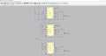
I have to design 3 DC/DC converters for a FPGA board with 3 needed voltages,
1.2 V, 1.8V and 3.3 V with 5 volts input. I have selected LTM4623.

What bothers me about the LTM4623 is that it is limited to 0.5A input current.

This means that certain output currents are not possible at all. Could you please help me, how can come out with 5 V input voltage and 0,5A input current e.g. 1,2V output with 3 A output current?

Thank you very much
best regards
Somayeh
 

Attachments

Papabravo

Joined Feb 24, 2006
22,082
It is not the value of the current that is important, but the immutable rule of power conversion:

The output power will always be less than the input power. Sometimes it will be much less.

Your input power is 5 Volts times 0.5 Amperes for 2.5 watts. If we assume the process is 80% efficient that will allow 2.0 watts of output power. So:
@3.3 Volts you have 0.61 watts​
@1.8 volts you have 1.11 watts​
@1.2 Volts you have 1.67 watts​
That is if you use one device for each voltage, you clearly cannot do three devices with one LTM4623. You can use 3 separate parts if you want, or you can keep looking.
 

BobTPH

Joined Jun 5, 2013
11,515
TI has a great design tool fir their switcher chips on their web site. Just put in the inputs and outputs and it will give you multiple designs with different strengths / weaknesses.

Bob
 

ronsimpson

Joined Oct 7, 2019
4,691
What bothers me about the LTM4623 is that it is limited to 0.5A input current.
I think you are looking at page 3. This is for a 12V to 1.5V 3A application. The current limit is the 3A out not current input.
In another spot they show a 5V to 3.3V@3A circuit which would draw 2A from the 5V.
There are several spots of 5V to some low voltage where the output is 3A.
 

Thread Starter

somaye2022

Joined Mar 23, 2022
100
It is not the value of the current that is important, but the immutable rule of power conversion:

The output power will always be less than the input power. Sometimes it will be much less.

Your input power is 5 Volts times 0.5 Amperes for 2.5 watts. If we assume the process is 80% efficient that will allow 2.0 watts of output power. So:
@3.3 Volts you have 0.61 watts​
@1.8 volts you have 1.11 watts​
@1.2 Volts you have 1.67 watts​
That is if you use one device for each voltage, you clearly cannot do three devices with one LTM4623. You can use 3 separate parts if you want, or you can keep looking.
Thank you for your reply, but I need 3A output current. It means, @1.2V and 3A it use 3.6 watt .
 

Thread Starter

somaye2022

Joined Mar 23, 2022
100
I think you are looking at page 3. This is for a 12V to 1.5V 3A application. The current limit is the 3A out not current input.
In another spot they show a 5V to 3.3V@3A circuit which would draw 2A from the 5V.
There are several spots of 5V to some low voltage where the output is 3A.
Thank you, that's right. Your tips are getting kind of useful for me. Now I have another challenge, page 19 shows the derating without heat sink. If I want to avoid derating, we have to use a heat sink. But that doesn't work for our boards. What do you think about this? Is that necessery?
 

Papabravo

Joined Feb 24, 2006
22,082
Thank you for your reply, but I need 3A output current. It means, @1.2V and 3A it use 3.6 watt .
Yes, that is correct. For design purposes you need more than 3.6 watts of input power. So 3.6/0.8 = 4.5 watts. It is possible with careful design and layout that you can do better than 80% efficiency. The closer you get to 100% the harder it gets to make improvements. That is why I always plan for 80% as a starting point.
 

ronsimpson

Joined Oct 7, 2019
4,691
I use the PCB as a heatsink. Look at this top side PCB design. I use thick copper. Use copper on all layers to move the heat to the back side of the board. Use VIAs to carry heat.
Look at the ground in the center bottom. Copy that pattern to all layers. That is part of the heatsink.
The Vout and Vin, do the same. I know that there are traces goi8ng to Rs and Cs that need to cut through power planes to get out but try to make the board mostly copper.
1649162541471.png
 

Thread Starter

somaye2022

Joined Mar 23, 2022
100
Thank you all for your reply , I hope it works well (I didn't find unfortunattly a better solution) because with my requirment ( 5 volt input 1.2, 1.8, 3.3V output and 4 MhHz switching frequency for an ultra thin camera boards) , and I have now another challenge . Currently I simulate 3 of them together with PHModes, CLKin, CLKout from Datasheet for 3 output voltages and for 120 phase shift but I don't know why it takes from input supply 9A current at once through CM even though I used application note 77 and phase shift, in order to not too much current (about 9A) in one time overlay . In the attachment is the results. beside that my Boss will to know, how is the Input current for every DC-DC Converter.

Thank you
best Regards
Somayeh
 

Attachments

ronsimpson

Joined Oct 7, 2019
4,691
I think you are trying to get 20 watts form 5V. The average current (input) is about 4A maybe 4.5A and the peak is about 9A.

I do not see any phase shift. This should help the peak current and not the average.

Cleaver how you bring up the 3.3V first.
 

ronsimpson

Joined Oct 7, 2019
4,691
It looks like the 3 supplies start at different time. ok

To lower the peak current on the 5V you will need a CLC filter. At each IC you need a cap, low ESR, low ESL. The cap needs to supply 4A to the IC. You need a cap on the 5V and an inductor to separate the 5V from the ICs.

I added a 10uF cap to each IC and a 0.22uH coil over to the 5V supply. I think there needs to be more capacitance. The coil is more than enough to reduce the ripple current on the supply.
 

Thread Starter

somaye2022

Joined Mar 23, 2022
100
It looks like the 3 supplies start at different time. ok
Hi,
thank you for your reply.

my boss wants to start a syncrone progression of input currents and with phase shift of 120 for three the input currents, but I have PHMode of ground for three phase mode as it said in the datasheet, but it dosent work. Could you please let me know why?

thank you with best regards
Somayeh
 

drjohsmith

Joined Dec 13, 2021
1,601
Hi,
thank you for your reply.

my boss wants to start a syncrone progression of input currents and with phase shift of 120 for three the input currents, but I have PHMode of ground for three phase mode as it said in the datasheet, but it dosent work. Could you please let me know why?

thank you with best regards
Somayeh

The LTM4623 is a great part
It also has reliable design / modelling tools,
dot add more / less filtering than the tools give you ,

Thermal
is always a problem ,
most of the design process now days is how to minimise the heat and get the heat out,
look at how warm your tablet PC runs !

You have learnt the main rue of DCDC,
power out is always less than power in
and there is no input current limit on these DCDC,
like most designs, its limited by the output / efficiency

Assuming your synchronising the DCDC's
and using the phmode pins,
this phase shifts the sync out for the next DCDC, so they are switching at different times, though synchronous, and as such lower the noise generated on the input power.
as per Fig 3 of the data sheet

It would be good to put the two DCDC that take the highest power on opposite phases,
to minimise this noise.

Follow closely the PCB layout notes to get good results,

One other thing
Check ow many of these you need when,
The pre order time on most DCDC is currently horrendous for any sort of quantity
 

Thread Starter

somaye2022

Joined Mar 23, 2022
100
Can you expand on what you want to simulate please ?
and what you understand the tools can't do ?
I wants to start a syncrone progression of input currents for every IC and with phase shift of 120 for three the input currents of every ICs, but I have PHMode of ground for three phase mode as it said in the datasheet with CLKin, CLKout, but it dosent work.
 

Attachments

ronsimpson

Joined Oct 7, 2019
4,691
The input current can be seen by adding a o ohm resistor or 0 inductor to each input. Some SPICE programs might not like 0 so use 0.001 ohm. Now you can see the current of each.
 
Top