DC-DC Converter

Thread Starter

somaye2022

Joined Mar 23, 2022
100
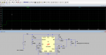
Hi all, I should design a DC-DC converter with LTC3412A for an FPGA board, this could provide 2,5 V DC output from 5 V DC input (the picture is uploaded). But I have no idea where to connect an AC signal and if it is even needed?
Secondly, there is a problem with the current in the inductor, I do not know how to fix it? Refer to the figure.

2022_03_23_13_29_06_DC_Regler_Spec._OneNote.png2022_03_23_13_31_28_LTspice_XVII_Draft1.png
Thanks in advance
With best regards
 

AnalogKid

Joined Aug 1, 2013
12,077
What is the required output current for the FPGA?

Why do you assume you need a switching regulator? At low output currents, this part is less than 50% efficient.

There is no load on the output. The circuit is characterized down to a load of 10 mA, but you do not have even that low amount. Are you running in Burst mode?

ak
 

Thread Starter

somaye2022

Joined Mar 23, 2022
100
What is the required output current for the FPGA?

Why do you assume you need a switching regulator? At low output currents, this part is less than 50% efficient.

There is no load on the output. The circuit is characterized down to a load of 10 mA, but you do not have even that low amount. Are you running in Burst mode?
Thank you for your reply.

To be honest with you, actually it is my first design from work, I am new in there. And there is a Camera and FPGA board for it.
This requires 1.2V Input voltage, and I need to design this DC/DC converter with selected IC of LTC3412A which can convert 5V of input to 1.2V as output for the input of FPGA with dynamic load current up to 4 Amps. This is my task!
I don't have chosen Burst Mode, I have chosen at the first basic Mode from the data sheet. I'm not confident, if Burst Mode is a better Option?

Best regards
 

ronsimpson

Joined Oct 7, 2019
4,658
Burst mode should only happen at very light load. Probably does not matter for now.
Do you know how to change the FB resistors to get 1.2V?
 

Papabravo

Joined Feb 24, 2006
22,061
Thank you for your reply.

To be honest with you, actually it is my first design from work, I am new in there. And there is a Camera and FPGA board for it.
This requires 1.2V Input voltage, and I need to design this DC/DC converter with selected IC of LTC3412A which can convert 5V of input to 1.2V as output for the input of FPGA with dynamic load current up to 4 Amps. This is my task!
I don't have chosen Burst Mode, I have chosen at the first basic Mode from the data sheet. I'm not confident, if Burst Mode is a better Option?

Best regards
Do you understand the underlying principles of how a buck converter works? The voltage at the SW (SWITCH) output is supposed to alternate between two values. One value will be higher than the desired output voltage and one value will be lower. The output voltage will be the time weighted average of those two values. The controller chip will adjust the duty cycle of the waveform at the SW output to make the output voltage equal to the desired value.

IMHO, for a first design I would go for one called CCM which stands for continuous conduction mode. This avoids a number of problems that a first time designer should not need to grapple with. It is also easier to understand conceptually.

If all of this sounds like Greek to you, it may help to go back and learn what you should have learned before you got thrown out of the frying pan and into the fire.

I recommend you study the schematic of the demo board thoroughly, until you know it like the back of your hand.
 
Last edited:

ronsimpson

Joined Oct 7, 2019
4,658
I do not understand your use of a current source load.
The numbers, I do not understand 90n Seconds? 25n Seconds?
Please just use a 1.2 ohm resistor for now.
---edited----
Use uS or mS (25mS, 90mS) reverse the two numbers.
 

Papabravo

Joined Feb 24, 2006
22,061
Thank you, this was really helpful. But what about the output current? I will have a Converter with a 4 A current load.
The way a load interacts with a DC-DC converter is that whatever is required is supplied by the DC-Dc converter as long as it is within the capability of the input voltage supply. What this means is that if the DC input can supply 100 watts and no more, you cannot ask for an output of 125 watts. That won't work. To use a Star Trek analogy:

The prime directive of DC-DC converters is that: "The output power will always be less than the input power. Sometimes it will be a great deal less". For a "back-of-the-envelope" initial design I always use 80% as a prospective efficiency factor. If the input supply has sufficient power and you control the losses through careful design and layout, then the output power will take care of itself.
 

ronsimpson

Joined Oct 7, 2019
4,658
As I said, I will have a Converter with a 4 A current load. How should I manage 4A at the Load?
Ohm law.
You have 1.2V, you want 4A, what resistor?
1.2V 1 ohm = 1.2A
1.2V 0.5 ohm 2.4A
1.2V 0.25 ohm 4.8A
Kets try three 1 ohm in parallel. 1.2V 0.333ohms, 3.6 A
Lets try 0.3 ohm, 4A
My head hurts today so did not do the math just tried and guessed, to find the answer.
Sorry I don't know how much you know about Ohm's law.
 

Thread Starter

somaye2022

Joined Mar 23, 2022
100
The circuit needs an AC supply voltage rectified to DC, Then connected to the input of the DC-DC converter.
Thank you for your reply, could you explain more or draw a circuit diagram relating to that, and please tell me how much should AC amplitude and frequency, or how could I manage these values?
 

eetech00

Joined Jun 8, 2013
4,704
Thank you for your reply, could you explain more or draw a circuit diagram relating to that, and please tell me how much should AC amplitude and frequency, or how could I manage these values?
How will the DC-DC converter be used?
The DC-DC converter is part of a larger design, right? First, Describe the purpose of the larger design.
 
Top