DC-DC Converter

Thread Starter

somaye2022

Joined Mar 23, 2022
100
Ohm law.
You have 1.2V, you want 4A, what resistor?
1.2V 1 ohm = 1.2A
1.2V 0.5 ohm 2.4A
1.2V 0.25 ohm 4.8A
Kets try three 1 ohm in parallel. 1.2V 0.333ohms, 3.6 A
Let's try 0.3 ohm, 4A
My head hurts today so did not do the math just tried and guessed, to find the answer.
Sorry I don't know how much you know about Ohm's law.
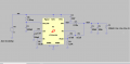
Thank you very much for your Answer, definitely I know Ohm's law, maybe I didn't explain the Task correctly (I'm so sorry). My task is to design and optimize this Regulator, but here it is also important to optimize readjustment for dynamic loads. And I didn't know how could I manage 4A at the output with a Dynamic Load?
 

Thread Starter

somaye2022

Joined Mar 23, 2022
100
How will the DC-DC converter be used?
The DC-DC converter is part of a larger design, right? First, Describe the purpose of the larger design.
Exactly, there is a camera, and this camera had an FPGA with too many blocks (8). Each block needs an accurate DC input voltage.

One of them needs an input voltage of 1.2 V with a current of 4 A. But the output of the DC-DC converter should be also optimized and able to tolerate dynamic loads.
 

Papabravo

Joined Feb 24, 2006
22,082
Exactly, there is a camera, and this camera had an FPGA with too many blocks (8). Each block needs an accurate DC input voltage.

One of them needs an input voltage of 1.2 V with a current of 4 A. But the output of the DC-DC converter should be also optimized and able to tolerate dynamic loads.
You're in over your head, and you need some help from the others in your organization.
 

Thread Starter

somaye2022

Joined Mar 23, 2022
100
You're in over your head, and you need some help from the others in your organization.
You are basically right, but the problem is that the person who could help me in this way is no longer there, and I must unfortunately manage my tasks and the challenges by myself.
 

ronsimpson

Joined Oct 7, 2019
4,693
Here I have a 1.2 ohm 1A load all the time and stepped the "I1" from 0 to3 and back several time. Here is a close up look at the voltage as the load does from 4 to 1A. I make the run time 10mS. The load steps from 1a to 4a in 10uS. Increased C1 to 100uF because there are probably many more capacitors on the 1.2V line around the FPGA. So C1=total of all capacitors.
It looks like the time constant in the error amp needs to be adjusted.
1648070839384.png
 

Papabravo

Joined Feb 24, 2006
22,082
You are basically right, but the problem is that the person who could help me in this way is no longer there, and I must unfortunately manage my tasks and the challenges by myself.
That is too bad. I see at least two possible outcomes:
  1. You do the best you can, and everything will be fine.
  2. You are being setup for failure, If so, you are better off bailing now before they get a chance to heap on the abuse to gaslight you and make you work for free to fix it.
There may be other outcomes, but those are the two that come to mind.
 

Thread Starter

somaye2022

Joined Mar 23, 2022
100
Hello everyone, thank you all for your help so far. I could now manage the dynamic load and I have with input of 5V an output voltage set with 1,2 V, ererything goes well. But now the problem is the SW voltage, Vsw, will chang until 5V, which should change between 0-2.4 V and the current of the Inductor also changes up to 5A, although the IC tolerates the current up to 3A. I have no idea where the issue is?
P.S: I have attached the Results
Best regards
Somayeh
 

Attachments

eetech00

Joined Jun 8, 2013
4,705
Hello everyone, thank you all for your help so far. I could now manage the dynamic load and I have with input of 5V an output voltage set with 1,2 V, ererything goes well. But now the problem is the SW voltage, Vsw, will chang until 5V, which should change between 0-2.4 V and the current of the Inductor also changes up to 5A, although the IC tolerates the current up to 3A. I have no idea where the issue is?
P.S: I have attached the Results
Best regards
Somayeh
What issue?
The output won't current limit until the load reaches somewhere between 4.5 and 6 amps (per spec).

1648133745475.png
 

eetech00

Joined Jun 8, 2013
4,705
Thank you very much for your answer. Firstly, according to the datasheet, this IC can only go up to 3A, right?
That is the recommended MAX current. The IC can begin current limit at 4.5A.

Secondly, Vsw should work in the range between 0 and 2.4V until the average of 1.2V is reached, am I right?
Vsw will depend on the input supply voltage (2.25v-5.5v).
The output voltage will stabilize when the FB pin reaches 0.8v. For this design, the output will stabilize at 1.2v
 

Thread Starter

somaye2022

Joined Mar 23, 2022
100
Looking at the output voltage and the voltage at "SW" pin.
View attachment 263453
As I underestand, " The voltage at the Vsw (SWITCH) should alternate between two values. One value will be higher than the desired output voltage and one value will be lower. The output voltage is the time weighted average of these two values. The controller chip adjusts the duty cycle of the waveform at the SW output so that the output voltage matches the desired value. "This can also be seen in your simulation result for Vsw. Why my circuit could not achieve such resulats...what is the problem from your side? I mean, your circuit Vsw is between 0-5 V to reach 2.5 V output voltage, considering that Vsw of my circuit should be between 0 -2.4 V to reach 1.2 V, am I right?

Moreover, the graph of your design is continuously between these values, but my graph oscillates in certain times these slot.

Thank you for your help
best regards
Somayeh
 

Attachments

Thread Starter

somaye2022

Joined Mar 23, 2022
100
Thank you so much.
It looks like the time constant in the error amp needs to be adjusted. How could I do that?

best Regards
Somayeh
 
Top