Facebook
 Google
 GitHub
 Linkedin
Hi,
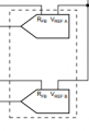
I'm getting a bit confused trying to figure out what components I need to connect the DAC714P in Bipolar mode ±10V This is the datasheet: http://www.ti.com/lit/ds/symlink/dac714.pdf On page 11 the wiring diagram is given for ±10V bipolar mode. On the right hand side are the following components given:

Could someone tell me if these should be the suggested D/As CMOS specified on the same page (11). And if this is true, these have 12-bit resolution wouldn't this be a problem while i'm using 16-bit. The DAC714P is 16-bit!
What I think is that these two components are one of the D/As CMOS, for example the DAC7800 : http://www.ti.com/lit/ds/symlink/dac7802.pdf and page 10 shows where to connect Vref A and Vref B and that a lot of other components are to be connected. There should also be a feedback loop towards Rfb A/B should that connection be in front of the C1 on the figure below?

Hope someone can help me with this, I'm making a prototype.
Best regards,
Dukel
I'm getting a bit confused trying to figure out what components I need to connect the DAC714P in Bipolar mode ±10V This is the datasheet: http://www.ti.com/lit/ds/symlink/dac714.pdf On page 11 the wiring diagram is given for ±10V bipolar mode. On the right hand side are the following components given:
Could someone tell me if these should be the suggested D/As CMOS specified on the same page (11). And if this is true, these have 12-bit resolution wouldn't this be a problem while i'm using 16-bit. The DAC714P is 16-bit!
What I think is that these two components are one of the D/As CMOS, for example the DAC7800 : http://www.ti.com/lit/ds/symlink/dac7802.pdf and page 10 shows where to connect Vref A and Vref B and that a lot of other components are to be connected. There should also be a feedback loop towards Rfb A/B should that connection be in front of the C1 on the figure below?
Hope someone can help me with this, I'm making a prototype.
Best regards,
Dukel