Current dependant load switch, cant solve it passively?

Thread Starter

Attenbach

Joined Jul 11, 2019
7
Hey there,

i couldn’t fall asleep trying to solve following scenario:
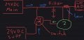
i have two power supplies running 24vdc in parallel, a main and one supplemental power supply. Both are being filtered with capacitors before supplying a single load.
Now if one wants to run it, such that the supplemental power source only supplies when the load draws a certain current, what does that circuit look like?
i was thinking of a mosfet switch but had no idea of how to drive it passively. Maybe an inline resistor after filtering, creating a voltage difference which gets amplified by an opamp which in turn will turn on the mosfet, when a certain voltage at the gate of the mosfet is achieved?
is there a faster, more practical/simple/efficient solution that doesnt require anything but off the shelf components and allows easy tuning of the current threshold at which the secondary supply helps out, maybe with a variable resistor?

The question above is just bugging me for no reason...really without practical applications.

Thank you for any insight!
ka
 

sghioto

Joined Dec 31, 2017
5,376
Maybe an inline resistor after filtering, creating a voltage difference which gets amplified by an opamp which in turn will turn on the mosfet, when a certain voltage at the gate of the mosfet is achieved?
On the right track but use comparator output to switch mosfets. Something like below.
SG
EEE P mosfet power supply switcher.png
 

ci139

Joined Jul 11, 2016
1,898
? do you need it like at the prev post or do you need 2 supplies on simultaneously starting from certain output power ?
( in the last case you may want to provide some balancing circuitry for your supplies . . . )
 

Thread Starter

Attenbach

Joined Jul 11, 2019
7
So that’s wha is boggling me. I am looking for a solution in the green circle. Both Power supplies are always on, with the supplemental one only being used when current above, say 10A.

simplest solution wins a cookie! :D
edit: I‘m currently on the road without my gear, sorry for the terrible sketch!
 

Attachments

Thread Starter

Attenbach

Joined Jul 11, 2019
7
So my solution looked as follows: the potential differerence across resistor Isens is amplified from 0.1v @ 10A to the threshold at which “load switch“ such as from Ti or Infineon are being activated. I don’t mind if the accuracy is +-1A. Would this even work?
 

Attachments

Reloadron

Joined Jan 15, 2015
7,501
If I were to do this using a pretty much turn key over the counter solution I would place a low side current shunt on my total load. I would have my current shunt drive a plane Jane process controller with relay output. When demand peaked above a pre set value I would bring my second supply online. I would allow some hysteresis in there. For example when my load demand exceeds 25 amps I bring my auxiliary supply online. It stays online until demand drops to 20 amps. A process controller I liked years ago was the Omega Engineering DP-41 but there are much less expensive process controllers designed to work with DC Current Shunts.

That or just design a roll your own using discrete components. Either way I would not lay awake and lose any sleep over it. :)

Not sure what you are getting at with the word "passively" in there. Any solution I can think of will involve both passive and active component use.

Ron
 
Last edited:

Thread Starter

Attenbach

Joined Jul 11, 2019
7
If I were to do this using a pretty much turn key over the counter solution I would place a low side current shunt on my total load. I would have my current shunt drive a plane Jane process controller with relay output. When demand peaked above a pre set value I would bring my second supply online. I would allow some hysteresis in there. For example when my load demand exceeds 25 amps I bring my auxiliary supply online. It stays online until demand drops to 20 amps. A process controller I liked years ago was the Omega Engineering DP-41 but there are much less expensive process controllers designed to work with DC Current Shunts.

That or just design a roll your own using discrete components. Either way I would not lay awake and lose any sleep over it. :)

Not sure what you are getting at with the word "passively" in there. Any solution I can think of will involve both passive and active component use.

Ron
Sounds complicated, so I think I almost cracked it. On a party, someone advised me on using a Schmitt trigger (which as you said also includes hysteresis), and I am reading into different OpAmp circuits for the job.

With passive I mean a hardware- tunable standalone circuit, so a control loop is achieved without microcontrollers and things to program/communicate to.
 

Papabravo

Joined Feb 24, 2006
21,158
If the supplies are "slightly" adjustable you can use a single diode on the supplemental supply such that it won't draw any current until the voltage on the main supply starts to drop. Might have to experiment with settings and parts.
 

dl324

Joined Mar 30, 2015
16,839
With passive I mean a hardware- tunable standalone circuit, so a control loop is achieved without microcontrollers and things to program/communicate to.
An EE's definition would be different. We'd think you were talking about passive components like resistors, capacitors, inductors, etc. No semiconductors are passive.
 
Top