Don't need the solenoid to work but need some kind of indicator to see that the circuit is working.
What are using to check that the circuit is working?
Replace the 2N3055 with the 2N2222, keep all resistors at 10K
You will need a reverse-biased diode (cathode to Vcc, anode to Q3 drain) connected across the solenoid to protect Q3 from the back-emf spike when Q3 switches off.
Correct but sometimes with my circuit on the breadboard it latch ON when first powered up. I verified your issue and since have moved the cap to the base of Q1 and ground. You can leave the cap out if not experiencing the problem I had but be aware if it does.
What exactly is the resistance of the coil?
I don't think that 9 volt battery can deliver enough current.
I know the circuit works because I have tested it myself on a breadboard.
Must be an incorrect connection somewhere.
The best way to breadboard the circuit is in stages. Start with the H1 Q1,Q2 and H2 circuit. Get that working correctly before the next stage of H3 Q3, Q4 and Q5.
Another thought is the Q3,Q4 combo is latching when it gets power from Q2 which was the issue I was having. Try adding a 100nf cap from the base of Q1 and Q3 to ground.
Like I said connect the circuits in stages starting with the H1 Q1-Q2 and H2 connections. Using a LED to indicate when Q2 is latched ON by H1 and OFF by H2.
I see you are using different transistors what are those part numbers?
I wouldn't think the increased voltage would make any difference. Q3 and R7 are the parts that latch Q4 ON. I would suspect a loose connection on the breadboard.
Drop the voltage back to 17.8 volts to see if it still works.
For 80 volt Vcc you could use a 65 volt zener diode in place of R9. It would need to be rated at least 3 watts. Or three 22 volt, 1 watt zener diodes in series.
Change D1 to a 1N4003.
Shouldn't be getting hot. Do you have other circuits powered besides the A3144 circuits?
Voltage should be much higher. Cap C4 should be rated at least 100 volts.
C3 at 25 volts.
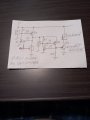
Please post your revised circuit.
Yes it would be best to just power the latch circuit with the 12 volts and use the 80 volts for the coil.
 Facebook
 Google
 GitHub
 Linkedin