 Facebook
 Google
 GitHub
 Linkedin
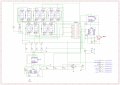
Hi everyone! I'm currently working on a digital alarm clock project and have used a website for reference: (https://bestengineeringprojects.com/digital-clock-with-seconds-and-alarm-time-display/) However, I've made some modifications, such as removing the transformer and some diodes. I've added a buzzer, a potentiometer, and a voltage regulator (7805). Currently, I'm using a 9V DC adapter, but since I'm just breadboarding everything for testing, I'm using a 9V power supply.
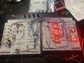
I've connected everything as shown in my schematic, but it seems not to be working. See the photo below:
*Note: I've also changed the capacitors in the original schematic from 47pF to 20pF since I am using an ATS042 4.9152 MHz ±30ppm Crystal 20pF 120 Ohms HC-49/US, which I bought from Digikey.
I'm open to any suggestions, comments, or advice about my schematic/circuit. I'm hoping to get this issue fixed as soon as possible
Attachments
-
 2.6 MB Views: 22
 -
 1.4 MB Views: 23


